Low-voltage application test method for fault current limiter valve set

A technology of fault current and limiter, applied in the field of power system, can solve the problem that the capacitor bank does not have and cannot obtain the forward conduction voltage

Active Publication Date: 2011-09-21
SHANGHAI MUNICIPAL ELECTRIC POWER CO +1
View PDF5 Cites 0 Cited by
  • Summary
  • Abstract
  • Description
  • Claims
  • Application Information

AI Technical Summary

Problems solved by technology

[0007] Problems currently existing: In the debugging stage, when there is no flow in the line, or when the fault current limiter FCL is not connected to the line, there is actually no voltage drop on the capacitor bank, and there is no voltage drop on the valve group. The voltage required for forward conduction cannot be obtained, so a new test method is needed to detect whether each valve can work normally during the debugging stage, and whether the action logic and action time meet the design requirements

Method used


Image

  • Low-voltage application test method for fault current limiter valve set
  • Low-voltage application test method for fault current limiter valve set
  • Low-voltage application test method for fault current limiter valve set

Examples


Embodiment Construction

[0021] In order to better understand the technical content of the present invention, specific embodiments are given and described as follows in conjunction with the accompanying drawings.

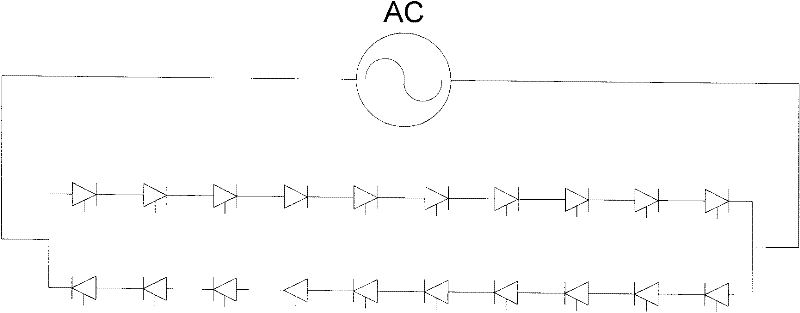
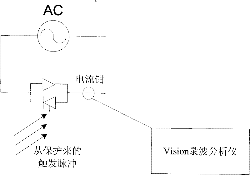
[0022] This test method involves the technology of how to test whether the thyristor valve element can be correctly triggered to conduct in the power system. Under normal operating conditions, the conduction of the valve element requires a certain forward pressure drop, that is, there must be a certain pressure difference on both sides of the valve group, but in the debugging stage, there is no current on the line, and no pressure can be formed on both sides of the valve group. Poor, so even under the conditions of protection triggering and laser energy acquisition, the valve element cannot be properly conducted. Therefore, it is necessary to check that the connection between the control protection, VBE, TE, TM and valve components is correct, and that the valve components can be correctly ...


PUM


Abstract

The invention provides a low-voltage application test method for a fault current limiter valve set. All thyristor valve elements can be normally conducted by changing short-circuit elements of a thyristor valve set and gradually testing a conduction situation of each thyristor valve element one by one. By the method, that whether the thyristor valve elements are trigged and conducted correctly, whether each thyristor valve works normally in a debugging stage and whether the operation logic and the operation time are in accordance with a design requirement can be detected; therefore, the correctness of the whole logic relation and the valve element functions can be guaranteed.

Description

technical field [0001] The invention relates to the field of power systems, and in particular to a low-voltage pressurization test method for a fault current limiter valve group. Background technique [0002] The thyristor valve is the most critical component in the fault current limiter, it is responsible for fast bypassing the series capacitor. The thyristor valve is controlled and protected by the control system. The input of the control system is the current in the series capacitor of the fault current limiter and the current in the thyristor valve; the output is the trigger pulse of the thyristor valve. [0003] The thyristor valve group is composed of 10 valves in forward series and 10 valves in reverse series and then parallel connection. Under the condition of triggering, when the energy harvesting works normally, under the action of AC voltage, the forward group is turned on in turn, and then the reverse group is turned on, so as to ensure that it can be turned on...

Claims


Application Information

Patent Timeline
Patent Type & Authority Applications(China)
IPC IPC(8): G01R31/02H02H9/02
Inventor 曾平鲍伟吴建坤沈冰
Owner SHANGHAI MUNICIPAL ELECTRIC POWER CO
Why Eureka
Try Eureka