
Five-freedom-degree precise position fixing device for adjustment of lens sets

A technology for precise positioning and fixing devices, applied in installation, optics, instruments, etc., can solve problems such as large accidental errors and poor optical axis consistency, and achieve the effects of low manufacturing cost, avoidance of accidental errors, and high positioning optical axis consistency.

Inactive Publication Date: 2011-09-21
HARBIN INST OF TECH
View PDF6 Cites 10 Cited by
  • Summary
  • Abstract
  • Description
  • Claims
  • Application Information

AI Technical Summary

Problems solved by technology

[0004] The purpose of the present invention is to provide a five-degree-of-freedom precision positioning and fixing device for lens group adjustment in order to solve the problems that the existing optical adjustment method has large accidental errors and the optical axis consistency of the optical product obtained by the adjustment is poor.

Method used


Image

  • Five-freedom-degree precise position fixing device for adjustment of lens sets
  • Five-freedom-degree precise position fixing device for adjustment of lens sets
  • Five-freedom-degree precise position fixing device for adjustment of lens sets

Examples


specific Embodiment approach 1

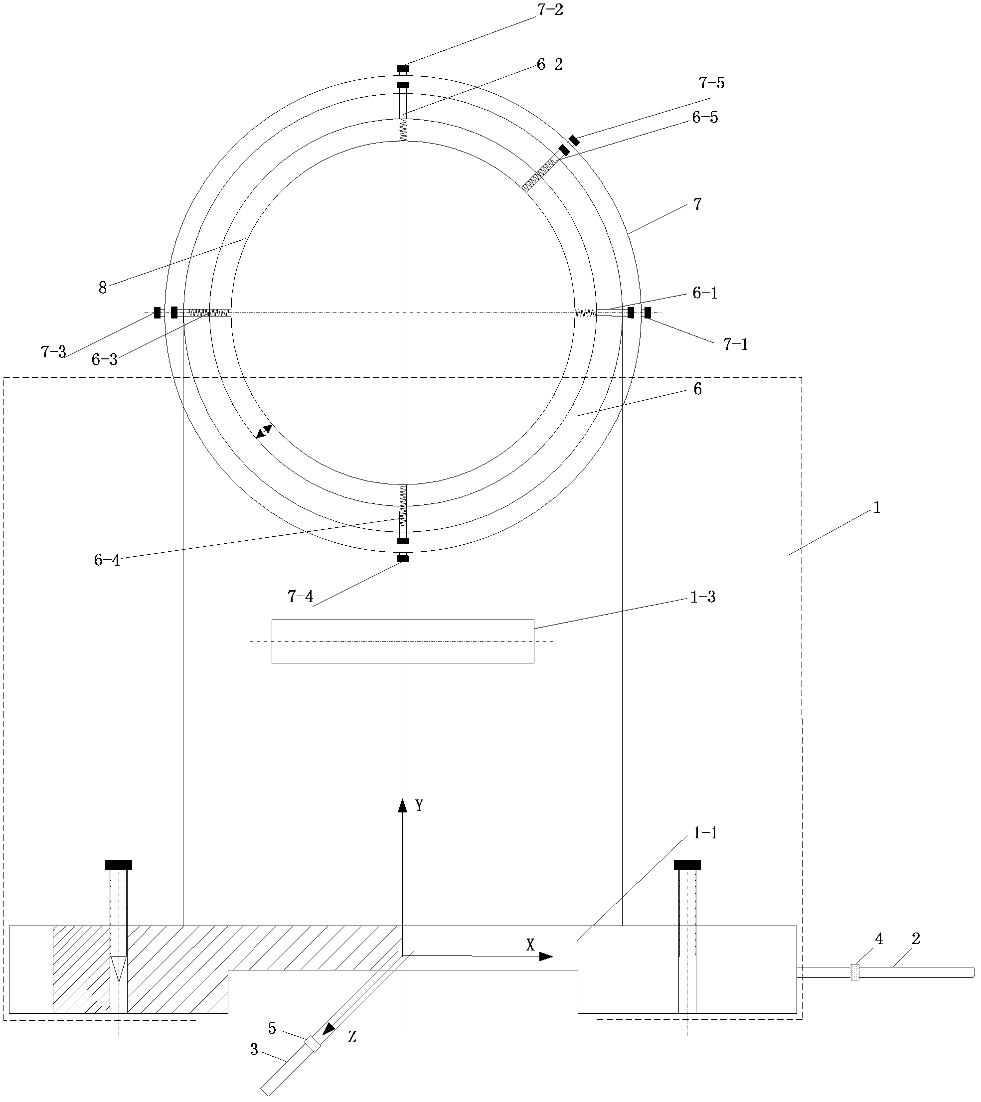
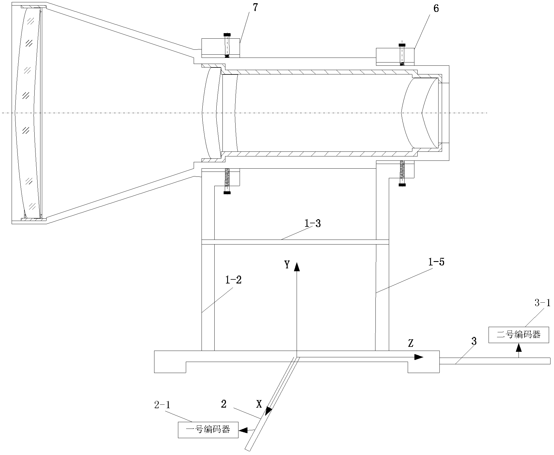
[0008] Specific implementation mode one: combine figure 1 and image 3 Describe this embodiment, this embodiment includes support base 1, No. 1 horizontal lead screw motor 2, No. 2 horizontal lead screw motor 3, No. 1 horizontal position sensor 4, No. 2 horizontal position sensor 5, No. 1 positioning and fixing ring 6, No. 2 positioning fixing ring 7, No. 1 positioning adjusting screw 6-3, No. 2 positioning adjusting screw 6-4, No. 3 positioning adjusting screw 7-3 and No. 4 positioning adjusting screw 7-4, No. 1 horizontal position sensor 4 setting On the No. 1 horizontal lead screw motor 2, the No. 1 horizontal lead screw motor 2 is connected to the bottom X-axis direction of the support base 1, the No. 2 horizontal position sensor 5 is arranged on the No. 2 horizontal lead screw motor 3, and the No. 2 horizontal lead screw motor The motor 3 is connected to the Z-axis direction at the bottom of the support base 1, the No. 1 positioning fixing ring 6 and the No. 2 positionin...

specific Embodiment approach 2

[0012] Specific implementation mode two: combination figure 1 and image 3 To illustrate this embodiment, the support base 1 of the first embodiment includes a horizontal base 1-1, a No. 1 vertical support plate 1-2, a No. 2 vertical support plate 1-5, and a horizontal fixed plate 1-3. No. 1-2 and No. 2 vertical support plates 1-5 are fixed on the two ends of the upper surface of the horizontal base 1-1 along the Z-axis direction, and the two ends of the horizontal fixed plate 1-3 are fixed on No. 1 vertical support plates 1-2 and No. 2 vertical support plates. No. vertical support plates 1-5 are in the middle of the opposite side surfaces. Other components and connections are the same as those in Embodiment 1.

specific Embodiment approach 3

[0013] Specific implementation mode three: combination figure 1 Describe this embodiment. The difference between this embodiment and Embodiment 1 is that it also includes No. 1 elastic fixing screw 6-1, No. 2 elastic fixing screw 6-2, No. 3 elastic fixing screw 7-1, and No. 4 elastic fixing screw 7-2, No. 1 locking screw 6-5 and No. 2 locking screw 7-5, No. 1 elastic fixing screw 6-1, No. 2 elastic fixing screw 6-2, No. 3 elastic fixing screw 7-1, and No. 4 elastic fixing screw The front ends of No. 1 elastic fixing screw 7-2, No. 1 snap screw 6-5 and No. 2 snap screw 7-5 are springs, No. 1 elastic fixing screw 6-1, No. The rear ends of the elastic fixing screw 7-1, the fourth elastic fixing screw 7-2, the first locking screw 6-5 and the second locking screw 7-5 are fixing screws, and the screws are screwed on the fixing ring in the radial direction And the front end penetrates the fixing ring, the No. 1 elastic fixing screw 6-1 is located at the right end of the No. 1 positi...


PUM


Abstract

The invention discloses a five-freedom-degree precise position fixing device for adjustment of lens sets, relating to a position fixing device for adjustment of lens sets, which solves the problem that the traditional optical adjustment method is more in accidental error and poor in consistency of an optical shaft of an adjusted optical product. The position fixing device comprises a supporting base, horizontal screw motors, horizontal position sensors, locating and fixing rings and positioning adjustment bolts; the first horizontal position sensor is arranged on the first horizontal screw motor; the first horizontal screw motor is connected with an X shaft at the bottom of the supporting base; the second horizontal position sensor is arranged on the second horizontal screw motor; the second horizontal screw motor is connected with a Z shaft at the bottom of the supporting base; the first locating and fixing ring and the second locating and fixing ring are fixed at two ends of the supporting base along the Z shaft; the front end of the positioning adjustment bolt is provided with a spring, the rear end of the positioning adjustment bolt is provided with a fixing bolt, the bolt is spun on the locating and fixing ring along a radial direction, and the front end of the bolt penetrates through the fixing ring. The five-freedom-degree precise position fixing device for adjustment of the lens sets is used for the precise positioning in adjustment of the lens sets.

Description

technical field [0001] The invention relates to a positioning and fixing device for lens group adjustment, which belongs to the technical field of optical adjustment. Background technique [0002] Optical assembly process technology has a direct impact on the performance of optical systems. With the increasing optical parameters and indicators of the optical system, the coaxial imaging optical system must achieve the imaging quality close to the diffraction limit. In the optical adjustment technology, the high-precision optical axis alignment technology has become a necessary means. [0003] The traditional optical adjustment method is to directly assemble the entire optical system, then qualitatively inspect the imaging quality of the optical system, and then determine the multi-dimensional adjustment direction and adjustment amount of the relevant components in the system according to the aberration characteristics and engineering experience. After the amount is adjusted,...

Claims


Application Information

Patent Timeline
Patent Type & Authority Applications(China)
IPC IPC(8): G02B7/02
Inventor 王治乐龚仲强谢蓄芬马秉鑫
Owner HARBIN INST OF TECH
Learn More