Projector and method for projecting an image by using the projector

A technology for projectors and images, which is applied in the field of projectors and can solve problems such as the inability to perform input terminal switching operations

Active Publication Date: 2011-09-21
SEIKO EPSON CORP
View PDF8 Cites 8 Cited by
  • Summary
  • Abstract
  • Description
  • Claims
  • Application Information

AI Technical Summary

Problems solved by technology

[0006] However, in the conventional projector, even if it is in the sleep (mute) state that temporarily stops image projection, once any operation is performed, the sleep state will be canceled immediately and the image projection will restart, so it cannot be performed while maintaining the sleep state. remote control etc.
Therefore, when an operation such as switching an input terminal is performed during an image display, etc., the viewer may see the screen being operated.
[0007] In addition, in conventional projectors, projection is not performed in the light-shielding state with the shutter closed, so there is a problem that the input terminal cannot be switched without opening the shutter once to put the projector in the projection state.

Method used


Image

  • Projector and method for projecting an image by using the projector
  • Projector and method for projecting an image by using the projector
  • Projector and method for projecting an image by using the projector

Examples


no. 1 approach

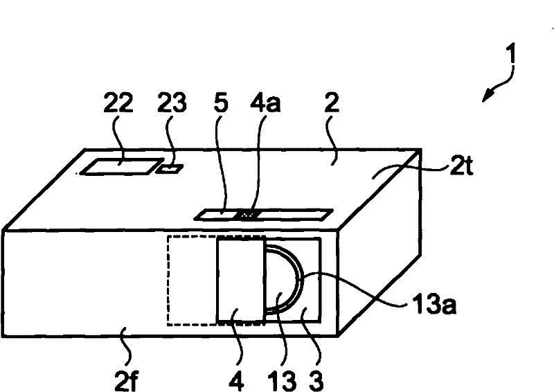
[0028] figure 1 It is a perspective view of the projector of this embodiment.

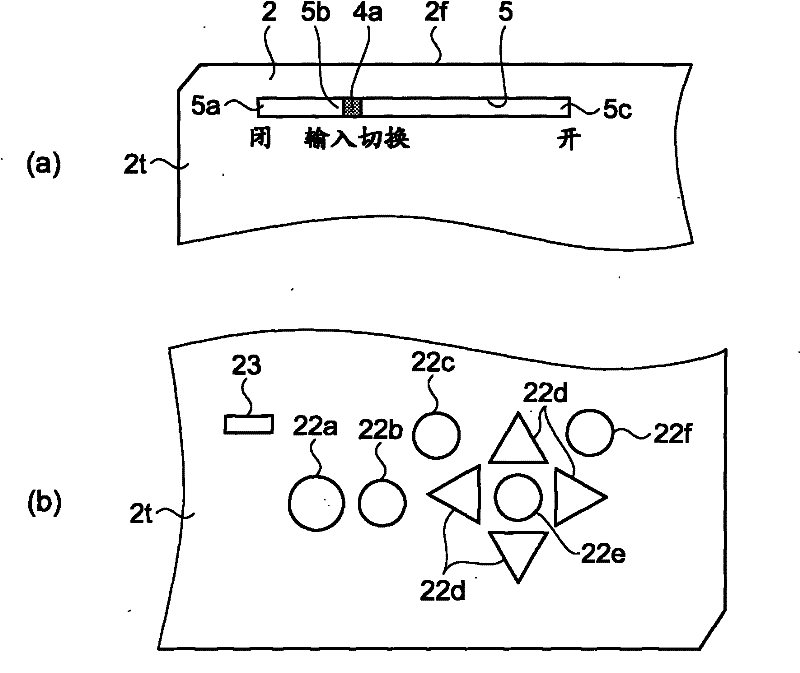
[0029] Such as figure 1 As shown, the projector 1 has a structure in which the main body of the projector is covered by the housing 2 . There is an opening 3 on the front 2f of the housing 2, and an input operation part 22 is provided on the upper surface 2t of the housing 2. The input operation part 22 has a plurality of operation keys for input operation by the user. , has an LED (Light emitting diode: light emitting diode) notification unit 23 for notifying the operating state of the projector 1 .

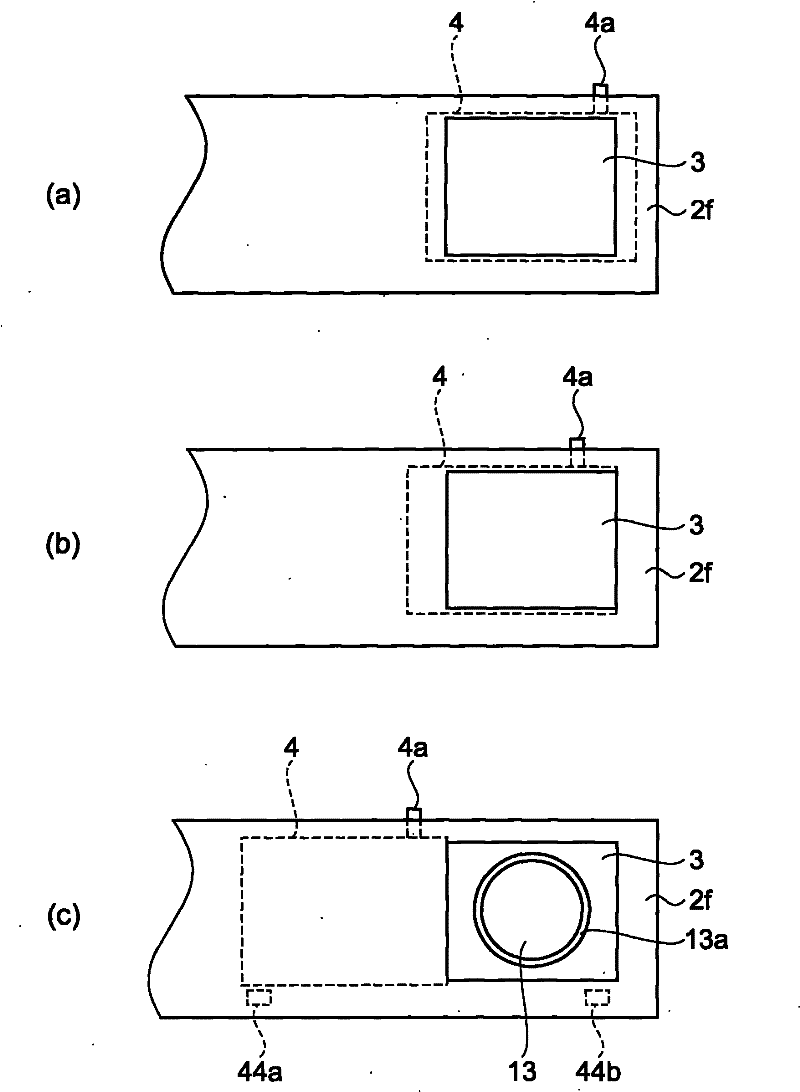
[0030] An opening 3 is formed on a front surface 2 f of the housing 2 , and a projection lens 13 for projecting image light forward is provided behind the opening 3 . The opening 3 is provided with a shutter 4 that can be opened and closed as a cover member. By closing the opening 3 with the shutter 4, the projection lens 13 is protected and projection light can be blocked. The shutter 4 is a sub...

Deformed example 1

[0068] In addition, the above-described embodiment may be modified as follows.

[0069] In the above-mentioned embodiment, in the sleep state, the input switching operation is performed on the image input terminal 25 that detects that the image signal is input to other terminals except the currently selected image input terminal 25, but it may also be detected in the sleep state. image input terminal 25, and stores information indicating a plurality of image input terminals 25 that have input an image signal, and displays a selection screen for selecting the image input terminal 25 when the sleep state is released, to operate and select the direction of the input operation portion 22 key 22d, decision key 22e. Figure 7 (a) to (c) show the operation screen at this time.

[0070] use Figure 6 The flow chart of the figure illustrates the operation of this modified example.

[0071] Such as Figure 6 As shown, first, when it is detected that the shutter 4 is slid from the op...

Deformed example 2

[0084] In the above-described embodiment, when it is detected that an image signal is input to a terminal other than the currently selected image input terminal 25 in the sleep state, the LED notification unit 23 may be notified. From such a configuration, it can be known whether or not an image signal is input to another image input terminal 25 in the sleep state in which the shutter 4 is closed. In this way, the shutter 4 is opened in a state where no image signal is input when the image display is switched, so that projection can be prevented from occurring.


PUM


Abstract

The invention provides a projector and a method for projecting an image by using the projector. In the projector, if an image signal other than the currently selected image signal is input, the image signal is switched to the other image signal according to the position of a shutter.

Description

technical field [0001] The present invention relates to a projector for projecting an image corresponding to input image data and an image projecting method. Background technique [0002] Projectors generally have a plurality of input terminals. For example, as described in Patent Document 1, when the user switches the currently selected input terminal to another input terminal through a remote control operation, the projected image is switched to another input terminal according to the input switching operation. The image corresponding to the image data from the newly selected input terminal. [0003] In addition, in order to prepare for the next image in the middle of image display, etc., the function of putting the projection of the image into a temporary sleep state is used. In addition to the method of projecting a black image in the sleep state, a method of arranging a sliding shutter in front of a projection lens of a projector to block light as described in Patent D...

Claims


Application Information

Patent Timeline
Patent Type & Authority Applications(China)
IPC IPC(8): G03B21/14G03B21/00H04N5/74
CPCG09G5/00H04N9/3179G03B21/14G02F1/13G03B21/00
Inventor 小沢孝
Owner SEIKO EPSON CORP
Why Eureka
Try Eureka