Device and method for carrying out field measurement on wave aberration of projection objective of photoetching machine adopting extended light sources

A technology of projection objective lens and extended light source, which is applied in the field of optical measurement, can solve the problems of low light source utilization rate, influence on measurement accuracy, poor light transmittance, etc., and achieve the effect of improving measurement accuracy, eliminating influence, and high utilization rate

Active Publication Date: 2012-11-07
BEIJING INSTITUTE OF TECHNOLOGYGY
View PDF3 Cites 0 Cited by
  • Summary
  • Abstract
  • Description
  • Claims
  • Application Information

AI Technical Summary

Problems solved by technology

However, the above-mentioned on-site measurement device has the following problems: First, it uses a pinhole mask containing a single pinhole to spatially filter the light beam. Due to the limitation of the light transmission area of ​​the pinhole, the light transmittance is poor and the utilization rate of the light source is low. , affecting the measurement accuracy
Second, it uses beam splitters and reflectors to change the optical path of the beam, and the loss of the beam is large during the propagation process

Method used


Image

  • Device and method for carrying out field measurement on wave aberration of projection objective of photoetching machine adopting extended light sources
  • Device and method for carrying out field measurement on wave aberration of projection objective of photoetching machine adopting extended light sources
  • Device and method for carrying out field measurement on wave aberration of projection objective of photoetching machine adopting extended light sources

Examples


Embodiment Construction

[0031] The present invention will be further described below in conjunction with the accompanying drawings and specific embodiments.

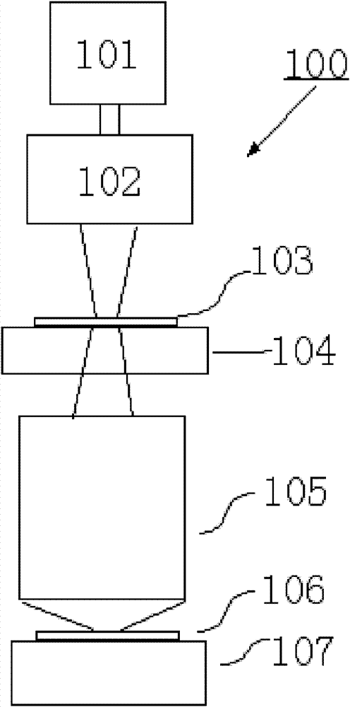
[0032] First introduce the lithography machine system, its structure diagram is as follows figure 1 As shown, it includes: a light source 101 , an illumination system 102 , a mask 103 , a mask stage 104 , a projection objective lens 105 , a silicon wafer 106 and a silicon wafer stage 107 .

[0033]The working principle of the lithography machine is as follows: after passing through the illumination system 102, the light emitted by the light source 101 is irradiated on the mask 103, and the pattern on the mask 103 is passed through the projection objective lens 105, and the projection is reduced in a "step-scan" manner. On the silicon wafer 106 coated with photoresist, so as to realize the pattern transfer. Wherein, the light source 101 is an excimer laser light source, such as an ArF excimer laser with a wavelength of about 193 nm or a KrF exc...


PUM


Abstract

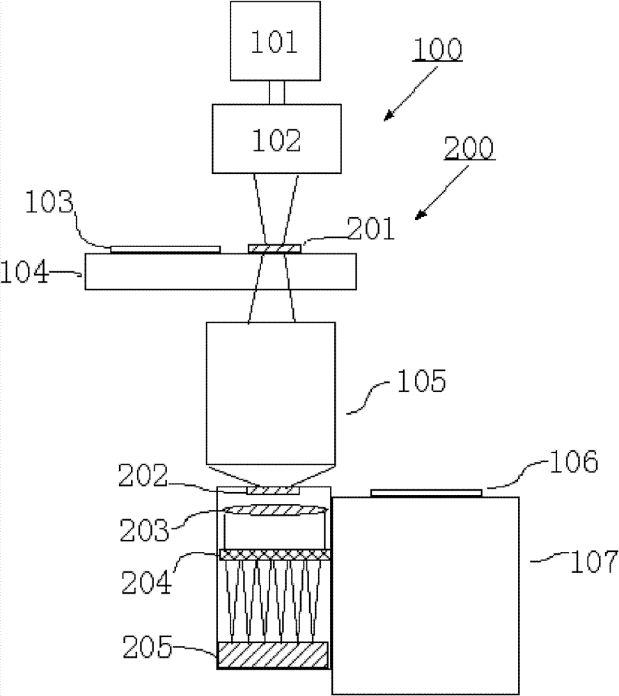
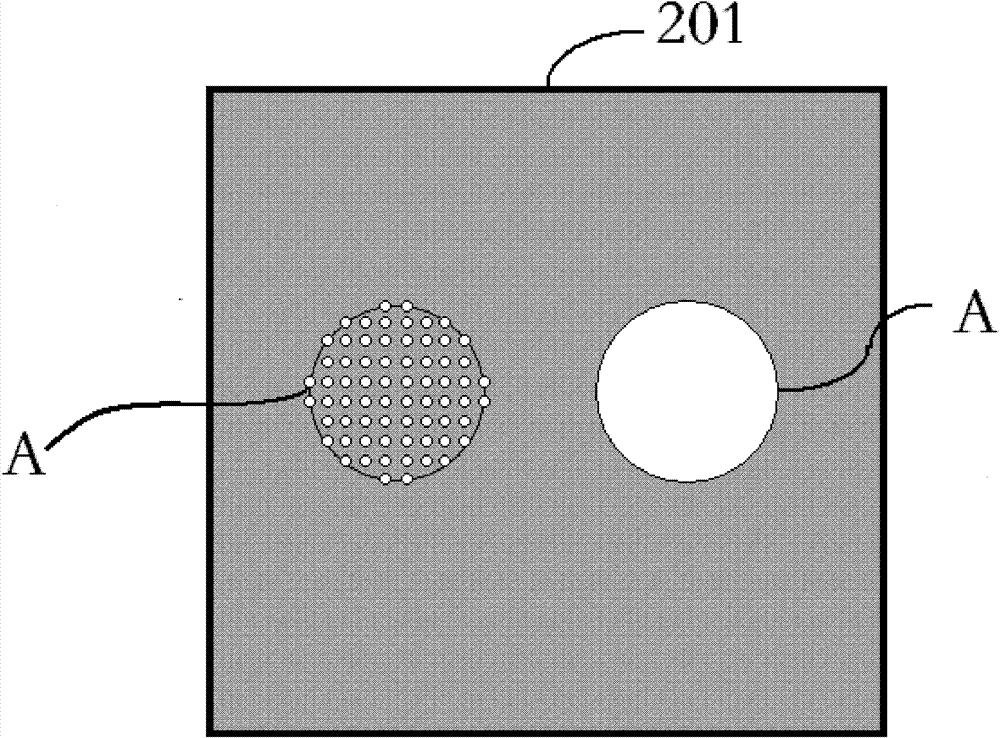
The invention provides a device and a method for carrying out field measurement on the wave aberration of a projection objective of a photoetching machine adopting extended light sources, and the high-precision detection on the wave aberration of a projection objective can be realized by using the device and the method. The method comprises the following steps: when detection on the wave aberration of the projection objective is carried out, generating ideal spherical waves by using a round pinhole array on a first extended light source board above the projection objective, thereby eliminating the influence on the detection on the wave aberration of the projection objective of the photoetching machine caused by an illuminating system; and when system error calibration is carried out, generating ideal spherical waves by using a round pinhole array on a second extended light source board below the projection objective, thereby realizing the spatial filtering of the residual aberration of an illuminating system to be tested and the wave aberration of the projection objective. In the invention, the round pinhole array is provided with a plurality of pinholes, so that the utilization rate of the light source is high; meanwhile, the loss of beams produced in the process of beam propagation is small, thereby improving the accuracy of measurement.

Description

technical field [0001] The invention relates to a device for on-site measurement of the optical performance of a projection optical system, in particular to a device for on-site measurement of the wave aberration of a projection objective lens of a lithography machine using an extended light source for illumination, and belongs to the technical field of optical measurement. Background technique [0002] In the manufacturing process of large-scale integrated circuits, a photolithography machine is usually used to reduce and project the pattern on the mask onto a silicon wafer coated with photoresist through a projection objective lens. Such as figure 1 As shown, the existing lithography machine generally includes a light source 101 for generating a projection beam; an illumination system 102 for adjusting the partial coherence factor and polarization state of the beam emitted by the light source; a projection that can image a mask pattern on a silicon wafer 106 The objective...

Claims


Application Information

Patent Timeline
Patent Type & Authority Patents(China)
IPC IPC(8): G03F7/20G01M11/02
Inventor 刘克李艳秋汪海王建峰
Owner BEIJING INSTITUTE OF TECHNOLOGYGY
Why Eureka
Try Eureka