
Termite trapping control device

A control device and termite technology, which is applied in the direction of trapping or killing insects, applications, animal husbandry, etc., can solve problems such as difficult to find, difficult to monitor in time, and small range of use

Inactive Publication Date: 2011-09-28
郑启洋
View PDF4 Cites 8 Cited by
  • Summary
  • Abstract
  • Description
  • Claims
  • Application Information

AI Technical Summary

Problems solved by technology

That is to say, when preventing termites in new house construction, in order to control termite damage, people use high-density stainless steel mesh to block around the building, and use car tanks to load pesticides to spray the soil around the wall foundation to form a toxic soil barrier and block the attack of termites. Serious environmental pollution and high cost
The fourth is to release termite traps and termite trap tubes. Although this method is simple and easy to do, it is difficult to find and easily lost. It is difficult to grasp the effect of killing termites. There are too many repeated sprays, which is difficult for scientific management. It is impossible to carry out long-term effective control and prevention of new termite colonies and newly invaded termite colonies; the fifth is to set up a monitoring box, which is difficult to place due to its large size, difficult to monitor in time, and the scope of use is small; sixth is to dig traps and spray powder to kill off
This method is more feasible for field construction, but it is difficult to kill under the conditions of dense population and hardened indoor and outdoor ground.

Method used


Image

  • Termite trapping control device
  • Termite trapping control device
  • Termite trapping control device

Examples


Embodiment 1

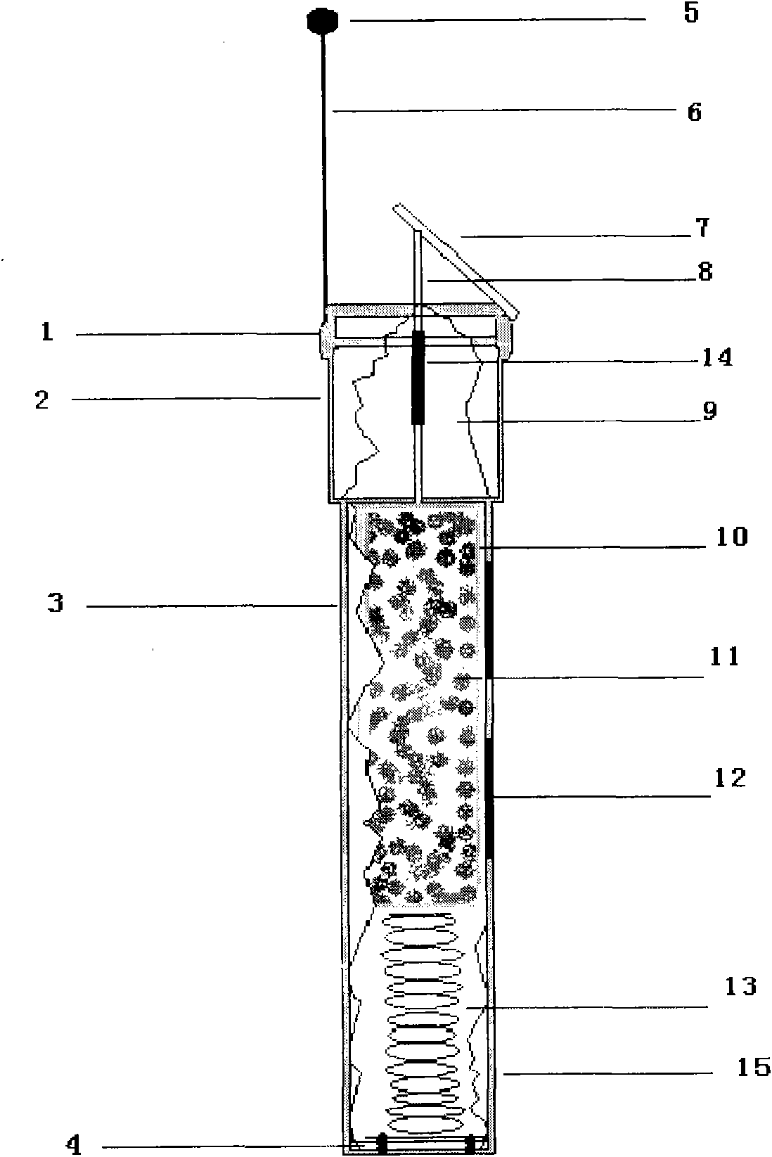
[0011] figure 1 : 1. Upper cover, 2. Upper tube, 3. Lower tube, 4. Bottom hole, 5. Indicating ball, 6. Upright rod, 7. Reflector, 8. Ejector, 9. Upper lumen, 10. Medicine Tube, 11, medicine, 12, access hole, 13, stage clip, 14, sleeve pipe, 15, outer casing.

[0012] The present invention consists of a perforated outer box 15, which is provided with a vertical rod 6 connected to the perforated outer box 15 and an indicator ball 5 at the upper end of the vertical rod 6; The reflecting mirror 7 that outer box body 15 is connected is used for people's long-distance observation or close-range inspection this utensil internal change situation. The lower part of the perforated outer box 15 is provided with a compression spring 13, on which is placed a drug tube 10 containing termite trapping and killing drugs; . When in use, open the upper cover 1, put the medicine tube 10 vertically on the compression spring 13 in the tube, cover the ejector rod 8 with the sleeve 14 connected to...

Embodiment 2

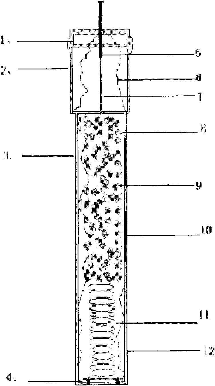
[0016] 6, vertical rod, 7, reflector, 8, upper cavity pipe, 9, medicament tube, 10, medicine, 11, access hole, 12, clip spring, 13, outer box body, 14, push rod.

Embodiment 2

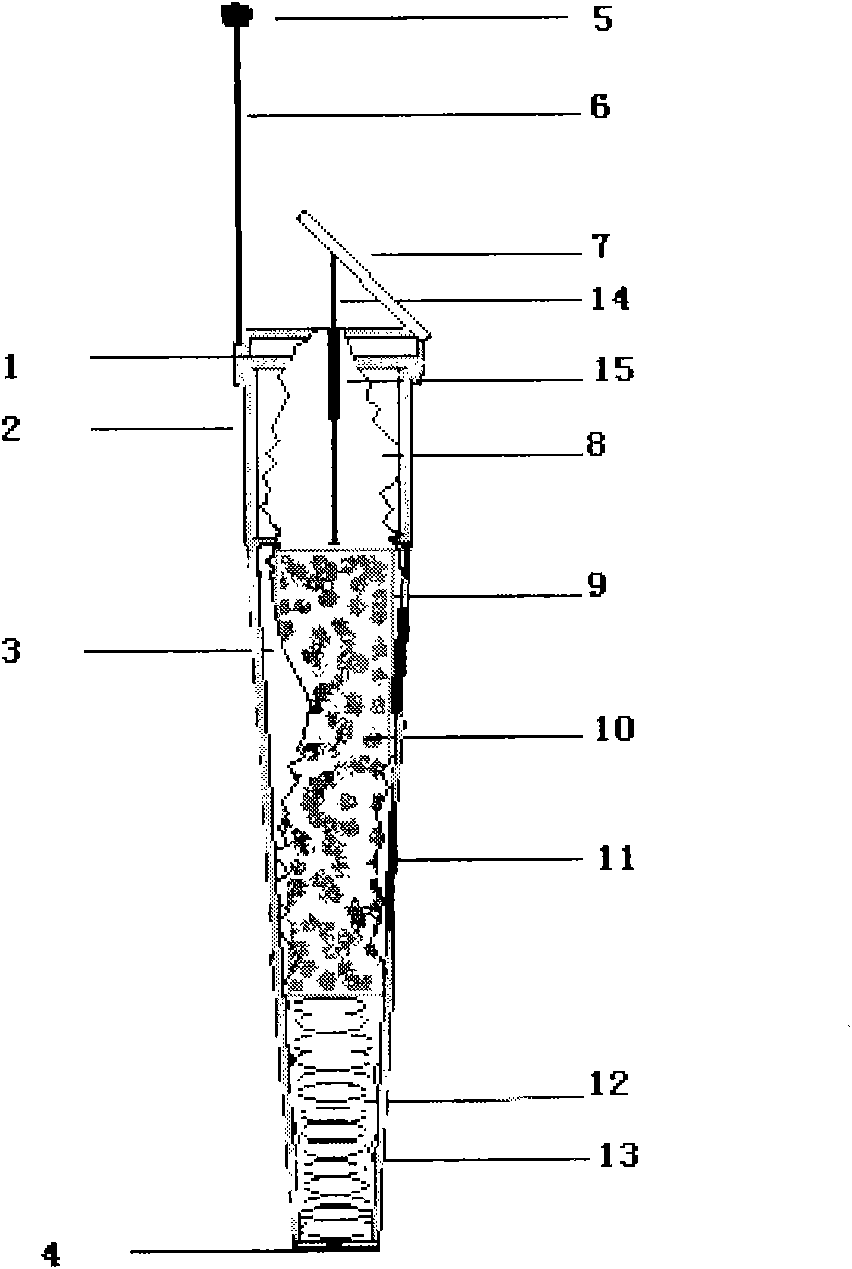
[0017] Embodiment 2 has basically the same structure as Embodiment 1. The difference is that the casing is omitted, and the appearance of the device has been changed to a funnel shape in order to facilitate drilling and embedding.


PUM


Abstract

The invention belongs to a mechanical control device for preventing and treating termites of industries of agriculture and forestry and buildings. A pressure spring is arranged in a perforated external box body; a drug tube used for containing termite trapping drug is arranged on the pressure spring; a vertical rod indicating ball and a reflector are arranged at the upper end of the external box body; power is stored in the box body for the termite trapping agent by the gravity pressure spring; after the termites eats the trapping agent, the down-pressing gravity is reduced, and the pressure spring pushes the drug tube and a push rod upwards so as to push the reflector or a signal pipe to display the signals of change of the interior of the box body. The termite trapping control device is easy and convenient to arrange and check, and is easy to manage scientifically and popularize; and the termite trapping drug is arranged in a tubular tool so that the drug is not easy to lose or leak and further not to cause pollution or harm human body, and can be recycled. The termite trapping control device disclosed by the invention is applicable to killing and prevention of termites of various places such as new or old buildings, gardens, medicinal fungus fields, farming fields, dams and the like.

Description

technical field [0001] The invention belongs to a mechanical control device for preventing and controlling termites in agriculture, forestry and buildings. It is mainly a device for long-term killing and control of termites by storing power in the gravity compression spring of the termite attractant in the box to promote the signal display outside the box. Background technique [0002] Over the years, the methods of preventing and controlling termites mainly include the following: one is to dig ant nests. This method is slow, labor-intensive, and easily damages buildings and the surrounding environment. The second is to spray termite powder. When the ant-killing powder kills termites, the dust will fly, which will easily damage the health of the builders and pollute the living environment. The third is to spray irrigation with pesticides. That is to say, when preventing termites in new house construction, in order to control termite damage, people use high-density stainl...

Claims


Application Information

Patent Timeline
IPC IPC(8): A01M1/20
Inventor 郑启洋
Owner 郑启洋
Learn More