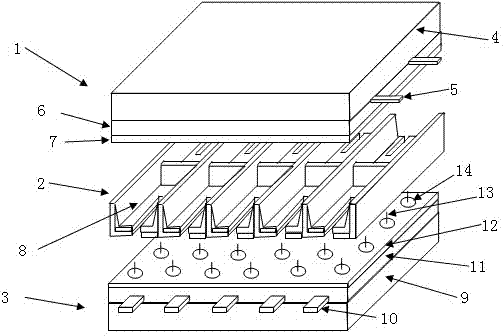
Shadow mask type plasma display panel

A plasma and display panel technology, applied in the direction of gas discharge electrodes, tube structural parts, discharge tubes, etc., can solve the problems of display panel brightness reduction and loss of phosphor powder area, etc., to improve brightness, improve utilization efficiency, and avoid mutual pollution effect

Inactive Publication Date: 2012-12-26
SOUTHEAST UNIV
View PDF3 Cites 0 Cited by
  • Summary
  • Abstract
  • Description
  • Claims
  • Application Information

AI Technical Summary

Problems solved by technology

However, the coating of carbon nanotubes (CNTs) on the surface of the phosphor does not affect the magnesium oxide (MgO), but the effective area of ​​the phosphor is lost, which directly causes the brightness of the display panel to decrease.

Method used


Image

  • Shadow mask type plasma display panel

Examples


example 1

[0025] Example 1: According to the above embodiment, the thickness of the porous alumina layer should be controlled between 0.5 and 1.5 microns, and CNTs with a length of 1 to 2 microns are used to ensure that the CNTs can form vertical orientation in the alumina pores, which is A first set of embodiments of the invention.

example 2

[0026] Example 2: According to the above embodiment, the diameter of the alumina pores should be controlled within 30-50 microns so that CNTs can smoothly enter the alumina pores. This is the second group of embodiments of the present invention.

example 3

[0027] Example 3: According to the above embodiment, CNTs can choose a single-wall structure or a multi-wall structure. This is the third group of embodiments of the present invention.


PUM


Abstract

The invention discloses a shadow mask type plasma display panel which is characterized by comprising a front panel (1), a rear panel (3) and a shadow mask (2) clamped between the front panel (1) and the rear panel (3), wherein the front panel (1) comprises a front glass substrate (4), a first electrode (5) positioned at the lower surface of the front glass substrate (4), an insulating medium layer (6) covered on the first electrode (5) and a protecting layer (7) covered on the insulating medium layer (6); the shadow mask (2) is provided with holes, and hole walls are coated with fluorescent powder (8); and the rear panel (3) comprises a rear glass substrate (9), a second electrode (10) and an insulating medium layer (11) covered on the second electrode (10). In the shadow mask type plasma display panel, the working voltage and the power consumption are reduced, and the brightness and the luminous efficiency are improved.

Description

technical field [0001] The invention relates to a structure of an opposite discharge color shadow mask type plasma display panel with high luminous efficiency, and belongs to the technical field of structural design of a color AC shadow mask type plasma display panel. Background technique [0002] At present, the key issues to be solved urgently in plasma display (PDP) are to improve luminous efficiency and reduce power consumption. The power consumption of the plasma display is mainly generated in the maintenance period. The power consumption in the maintenance period is related to the maintenance voltage and luminous efficiency. At present, the main ways to improve the luminous efficiency are as follows: one is to increase the total working pressure and xenon (Xe) partial pressure of the plasma display; the other is to optimize the structure of the discharge unit. The research results show that the power consumption has been reduced to a certain extent. The main way to ...

Claims


Application Information

Patent Timeline
Patent Type & Authority Patents(China)
IPC IPC(8): H01J11/40H01J11/22
Inventor 樊兆雯仲雪飞张雄
Owner SOUTHEAST UNIV
Why Eureka
Try Eureka