
Electronic device shell

A technology for electronic devices and housings, which is applied to electrical equipment housings/cabinets/drawers, electrical components, housings with display/control units, etc. Product cost increase and other issues, to achieve the effect of enhancing added value and use value, enhancing overall sense and beautiful appearance

Active Publication Date: 2011-09-28
JIANGSU WUWEI POLICE EQUIP MFG
View PDF4 Cites 14 Cited by
  • Summary
  • Abstract
  • Description
  • Claims
  • Application Information

AI Technical Summary

Problems solved by technology

Although the shell made by this method can avoid the gap between the window and the shell, and the bonding force between the window and the shell is also strong, but its disadvantage is that it needs to develop a mold, so that the product cost is raised
Moreover, due to the cost considerations, limitations and timeliness of mold development, it is not conducive to the diversity of housing structures of electronic devices, and it is difficult to adapt to the development trend of today's ever-changing appearance of electronic products

Method used


Image

  • Electronic device shell
  • Electronic device shell
  • Electronic device shell

Examples


Embodiment Construction

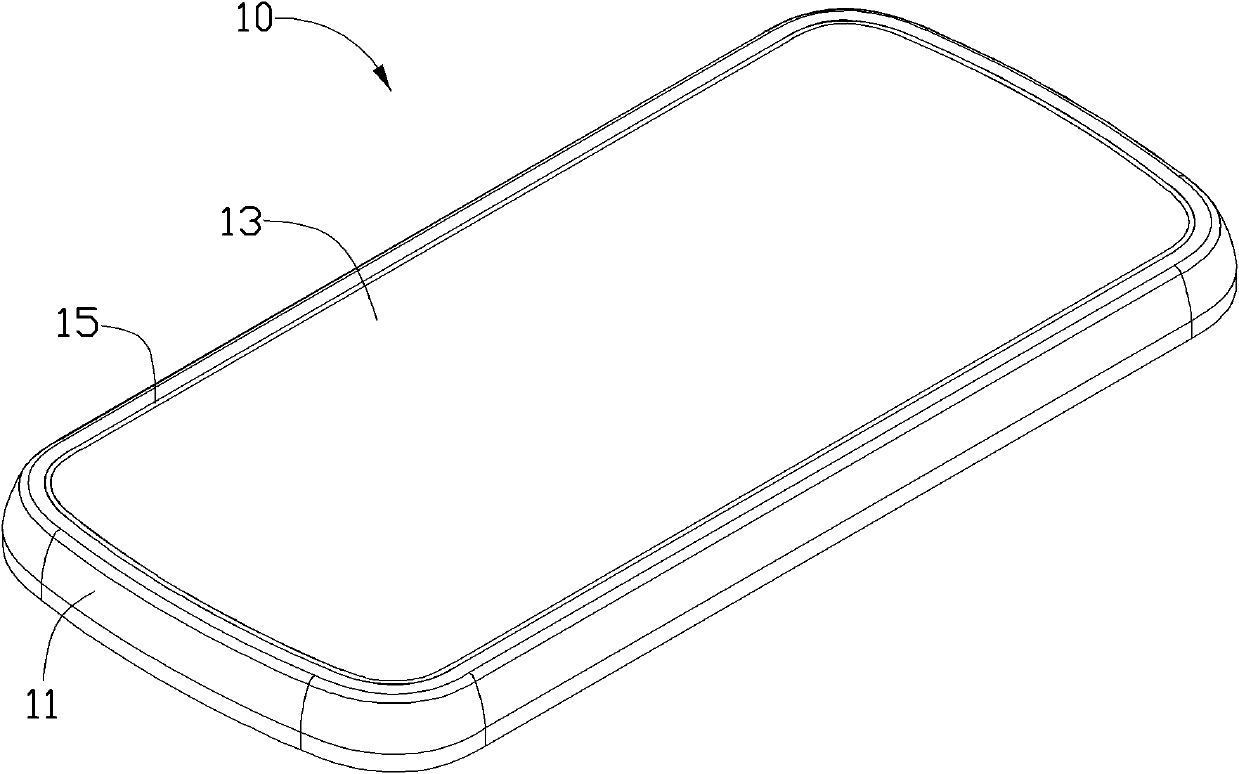
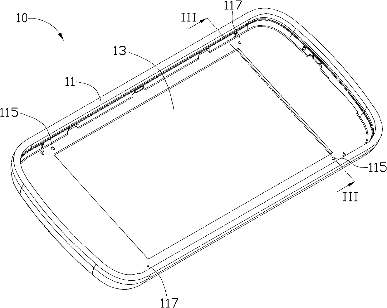
[0024] see Figure 1 to Figure 3 , The housing 10 of the electronic device according to a preferred embodiment of the present invention includes a housing part 11 , a window part 13 and an adhesive layer 15 . The window piece 13 is installed in the casing piece 11 , and the adhesive layer 15 is formed between the window piece 13 and the casing piece 11 .

[0025] The housing part 11 can be produced by injection moulding. The plastic used for injection molding the housing part 11 may be polycarbonate (PC), polymethyl methacrylate (PMMA) or polyamide (PA). These plastics have strong impact and scratch resistance.

[0026] The housing member 11 is formed with a rectangular window portion 111 . A step 113 is formed around the periphery of the window part 111 of the casing part 11 , and the step 113 is used for carrying the window part 13 . A plurality of openings are formed on the step 113 adjacent to the window portion 111 , and the plurality of openings include a plurality o...


PUM


Abstract

The invention provides an electronic device shell, which comprises a shell element and a window element. A window part is arranged on the shell element; the window element covers the window part; a gap is formed between the window element and the shell element; a plurality of open pores are formed at the position, adjacent to the window part, of the shell element; an adhesive layer is arranged in the gap; the adhesive layer is respectively combined with the shell element and the window element closely to fixedly connect the window element to the shell element; and the adhesive layer is formed by injecting viscose into the open pores and filling the viscose into the gap.

Description

technical field [0001] The invention relates to an electronic device casing, in particular to an electronic device casing in which a window part and a casing part are tightly combined. Background technique [0002] The conventional manufacturing method for an electronic device housing with a window is to first form a housing part with a window mounting hole, and then install the window part at the window mounting hole by sticking glue. Installing the window in this way will inevitably have an installation gap at the contact point between the window and the housing, which will affect the overall appearance and appearance of the housing. More importantly, dust, moisture and other debris will easily enter the electronic device through the gap. internal, and destroy the function of the product. At the same time, the windows of the housing of the electronic device manufactured by this method are also easy to fall off. [0003] Another method is to manufacture the housing by in-...

Claims


Application Information

Patent Timeline
Patent Type & Authority Applications(China)
IPC IPC(8): H05K5/00
CPCH05K5/0017
Inventor 谷长海何柏锋
Owner JIANGSU WUWEI POLICE EQUIP MFG
Learn More