Mount for solar cell module, and photovoltaic power generation system using the mount

A solar cell and pedestal technology, applied in the field of solar power generation systems, can solve the problems of small protrusions being skewed or crushed, weak in strength, and skewed, and achieve the effect of eliminating cumbersome operations and stably grounding

Inactive Publication Date: 2011-09-28
SHARP KK
View PDF9 Cites 9 Cited by
  • Summary
  • Abstract
  • Description
  • Claims
  • Application Information

AI Technical Summary

Problems solved by technology

[0006] However, as in Patent Document 1, the tiny protrusions that support the solar cell panel on the base without looseness are weak, and when the frame is pressed from above, the protrusions may become distorted before they sink into the frame.
Or, when the position of the frame of the solar cell module is adjusted after falling into the frame, or the frame of the solar cell module is shifted by collision, the micro-protrusions are skewed or crushed, and the solar cell module and the micro-protrusions cannot be stabilized. electrical connection
[0007] For example, when an aluminum material is used for the frame of a solar cell module, an insulating oxide film is formed on the surface of the aluminum. In the state where the oxide film on the surface is in contact, it becomes difficult to conduct conduction via the solar cell module frame with tiny protrusions

Method used


Image

  • Mount for solar cell module, and photovoltaic power generation system using the mount
  • Mount for solar cell module, and photovoltaic power generation system using the mount
  • Mount for solar cell module, and photovoltaic power generation system using the mount

Examples


Embodiment Construction

[0047] Hereinafter, embodiments of the present invention will be described in detail with reference to the drawings.

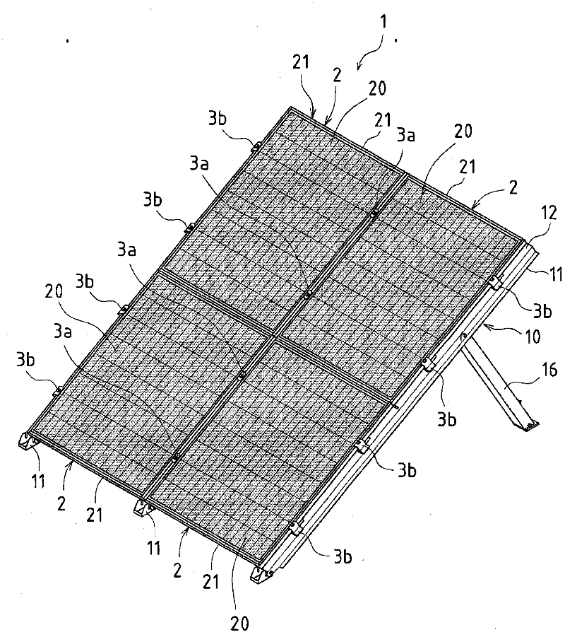
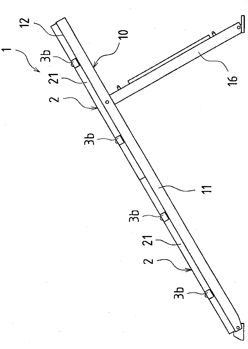
[0048] figure 1 It is a perspective view showing the first embodiment of the base of the solar cell module of the present invention. in addition, figure 2 It is a side view showing the base unit of the first embodiment.

[0049] In the base 1 of the solar cell module of the present embodiment, three such as figure 2 Shown base unit 10, these base units 10 are arranged side by side on roof, ground etc., as figure 1 As shown, four solar cell modules 2 are placed and fixed on each base unit 10 .

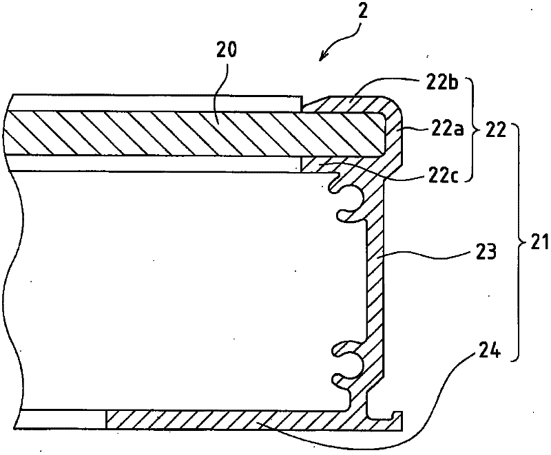
[0050] The solar cell module 2 is composed of a solar cell panel 20 and a frame member 21 holding the solar cell panel 20 .

[0051] Such as figure 2 As shown, the base unit 10 is composed of a mounting bracket 11 and a longitudinal bracket 16, and is formed in an inclined T-shape when viewed from the side. That is, one base unit 10 is formed by fixing the fro...


PUM


Abstract

A frame member (21) of a solar cell module (2) is fixed and supported by being sandwiched between a lower fixture (4) and an upper fixture (3a). A protrusion (44a) on an upper plate (40) of the lower fixture (4) is pressed to the surface of the frame member (21) of the solar cell module (2). When a bolt (8) is tightly fastened, the upper plate (40) and the frame member (21) are brought into strong contact with each other with pressure, and the protrusion (44a) on the upper plate (40) enters the surface of the frame member (21) of the solar cell module (2) and permits electricity to be carried.

Description

technical field [0001] The present invention relates to a base for fixing and supporting a solar cell module and a solar power generation system using the base. Background technique [0002] Usually, when a solar cell module is installed on a roof or the like, a base for the solar cell module is mounted on the roof or the like, and the solar cell module is placed on the base and fixed. On the other hand, the charged charge is grounded, and the frame structure of the solar cell module and the like are connected to the ground through wiring. [0003] However, since the frame structure of the solar cell module formed of a conductive metal body is provided with an insulating film for corrosion protection, the work of wiring the ground wire of the solar cell panel is cumbersome. In contrast, there has been proposed a solar cell panel mounting base in which the ground wire is grounded easily and reliably. [0004] For example, Patent Document 1 describes a technique of providing...

Claims


Application Information

Patent Timeline
Patent Type & Authority Applications(China)
IPC IPC(8): E04D13/18H01L31/042
CPCF24J2/5258H01L31/0422F24J2/5232F24J2/523Y02E10/50Y02B10/12Y02E10/47F24S25/10F24S25/636H02S20/10H02S20/23Y02B10/10
Inventor 嵯峨山健一
Owner SHARP KK
Why Eureka
Try Eureka