
Suspension spray arm structure for uncovering-type dish washing machine

A dishwasher and suspension technology, applied in the field of suspension spray arm structure, can solve the problems of low rotation efficiency, slow spray arm rotation speed, easy wear and tear of the central shaft, etc.

Inactive Publication Date: 2011-10-05
泰州浩邦科技发展有限公司
View PDF0 Cites 10 Cited by
  • Summary
  • Abstract
  • Description
  • Claims
  • Application Information

AI Technical Summary

Problems solved by technology

[0003] In the prior art, there is a water supply cavity inside the spray arm, and a water spray hole connected to the internal water supply cavity is opened on the upper surface of the spray arm. The water supply cavity is connected to the water supply sleeve connected to the water supply pump, and the spray arm passes through The mounting part in the center is installed on the central shaft, and the connection between the water supply cavity and the inner cavity of the water supply casing is a closed structure, which has the following disadvantages: 1. The fitting gap between the mounting part and the central shaft is about 0.1mm, and when the spray arm rotates with There is contact mechanical friction between the central shafts, and the central shaft is easy to wear. 2. The contact mechanical friction between the mounting part and the water supply sleeve supporting it has large friction force, slow speed of spray arm, and low rotation efficiency.

Method used


Image

  • Suspension spray arm structure for uncovering-type dish washing machine
  • Suspension spray arm structure for uncovering-type dish washing machine

Examples


Embodiment Construction

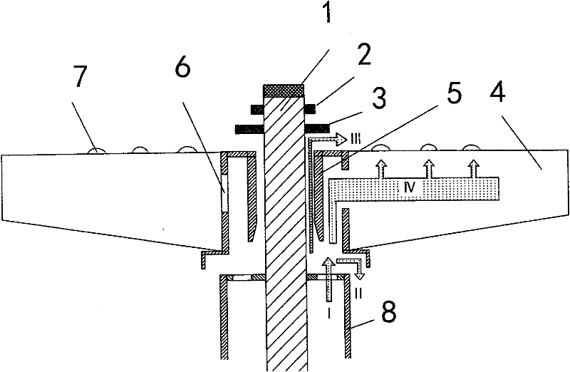
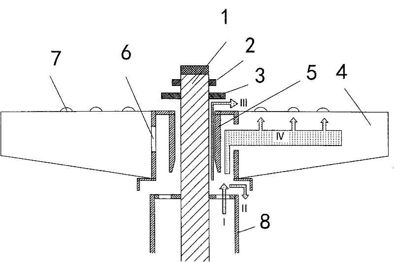
[0016] In the embodiment of the present invention shown in the drawings, it includes a spray arm 4 with a water supply cavity 6 inside and a spray hole 7 connected to the internal water supply cavity on the upper surface. The water distribution jacket 5 is movably installed on the central shaft 1. The inner diameter of the water distribution jacket 5 is 2mm larger than the outer diameter of the central shaft. The lower end of the water distribution jacket 5 is separated from the upper end of the water supply sleeve 8, and the water distribution jacket 5 is supported on the water supply jacket. Tube 8 on. Gasket 3 and circlip 2 are installed on the upper side of the water distribution jacket 5. The gasket 3 has an appropriate distance from the water distribution jacket 5, and is used to limit the position of the spray arm 4. When the water is pressurized by the water pump to the water supply casing 8 , the water flow has three directions, one is to enter the water supply cavity...


PUM


Abstract

The invention relates to a suspension spray arm structure for an uncovering-type dish washing machine. The structure comprises a spray arm, wherein the spray arm is internally provided with a water supply cavity and the upper surface of the spray arm is provided with water-spraying holes communicated with the internal water supply cavity, the spray arm is arranged on a center shaft by virtue of a water distribution sleeve at the center, the inner diameter of the water distribution sheath is slightly more than the outer diameter of the center shaft, wherein the outer diameter of the center shaft is 2-6mm, the lower end of the water distribution sleeve and the upper end of a water supply sleeve are in a separation structure, and the water distribution sleeve is supported on the water supply sleeve. When the suspension spray arm structure is in operation and high pressure water generated by a water pump enters into the water supply cavity from the water supply sleeve by virtue of the water distribution sleeve, a part of water flow can flow out downward from the lower side of the water distribution sleeve, the spray arm can be pushed to float upward by a reverse upward acting force generated by the spray arm, another part of water flow can flow out from a gap between the water distribution sleeve and the center shaft to form a water film layer, and lubrication is produced by the water film layer in a rotating process. The frictional force of the spray arm structure provided by the invention is greatly reduced, the center shaft is difficult to wear, and the rotating speed of the spray arm is fast.

Description

(1) Technical field: [0001] The invention relates to a suspended spray arm structure for a cover-opening type dishwasher, and relates to the technical field of dishwashers. (two) background technology: [0002] The lid-covering dishwasher consists of a lower shell, an upper cover with a handle installed on the upper end of the lower shell that can be opened and closed, a suspended spray arm installed inside the upper cover, a bowl basket, and a grid installed in the lower shell. It is composed of hot water tank, clean water tank, water pump and electrical box. The suspended spray arm is installed on the central rod, which is a hollow structure, and there is a water spray hole on it. The inner cavity of the suspended spray arm is connected to the outlet of the hot water pump through the water supply sleeve, and the opening direction of the spray hole faces the bowl. basket. When working, the hot water pump pumps out the hot water in the water tank, sends it into the hollow ...

Claims


Application Information

Patent Timeline
IPC IPC(8): A47L15/23
Inventor 韩春涛
Owner 泰州浩邦科技发展有限公司
Learn More