Die plate

A formwork and mold technology, applied in the field of formwork, can solve the problems of mold deformation, increased wear, etc., and achieve the effect of reduced length, reduced structural space, and avoiding replacement

Active Publication Date: 2011-10-05
FETTE COMPACTING GMBH
View PDF8 Cites 0 Cited by
  • Summary
  • Abstract
  • Description
  • Claims
  • Application Information

AI Technical Summary

Problems solved by technology

This is not good for maintaining the positioning of the mold and may cause deformation of the mold
As a result, the punches of the rotary press rub against the inner walls of the die, causing increased wear

Method used


Image

  • Die plate
  • Die plate
  • Die plate

Examples


Embodiment Construction

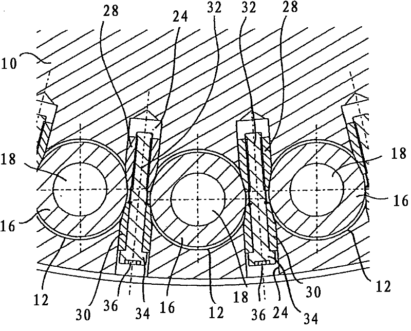
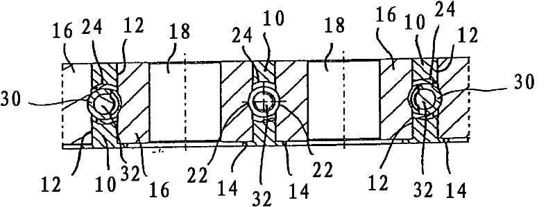
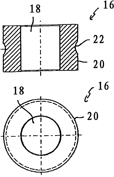
[0024] In the drawings, like reference numbers refer to like objects, unless otherwise indicated. figure 1 A portion of formwork 10 of the present invention is shown in horizontal section. figure 2 Parts of the formwork 10 of the present invention are also shown in vertical section. Template 10 is part of the rotor of a rotary tablet press (not shown). The template 10 shown in the example is designed to have a circular shape and can be rotated together with the rotor about a vertical axis of rotation. The formwork 10 has a plurality of die holes 12 which are distributed at regular intervals along the circumferential direction of the formwork 10 . exist figure 1 and 2 Among them, it can be seen that the die hole 12 is a cylindrical hole, and they are in figure 2 Each of them has an annular ring 14 at its lower end. The cylindrical mold 16 accommodated in the respective hole 12 rests in each case with its underside on the collar 14 of the hole 12 associated therewith. T...


PUM


Abstract

A die plate for the rotor of a rotary tablet press comprising a plurality of die holes, with dies provided therein, arranged distributed in the circumferential direction of the die plate, and between every two adjacent die holes radially running bores, in each of which a fastening device is disposed for fastening the dies, characterized in that at least one fastening device comprises two clamping elements disposed opposite each other in a radial bore, and a tensioning device, wherein the clamping elements can be tensioned against each other in the radial direction using the tensioning device, wherein the clamping elements are pressed against the dies adjacent to the radial bore.

Description

technical field [0001] The invention relates to a template for a rotor of a rotary tablet press, comprising: a plurality of die holes distributed along the circumferential direction of the template, a die is arranged in the die holes; radially extending holes between adjacent die holes, and a fastening device is provided in each said hole for fastening said mould. A known fastening device for fastening molds has a tapered pin and a set screw associated with the tapered pin. The tapered pins of the fastening device are respectively inserted into the radial holes of the formwork. Next, set screws are screwed into the radial holes, wherein the conical pins are each pressed against a die arranged adjacent to the radial holes. Background technique [0002] Said known fastening device has some disadvantages. For example, set screws are screwed into internal threads formed in radial bores from the circumferential outer side of the formwork, wherein they press the more inwardly a...

Claims


Application Information

Patent Timeline
Patent Type & Authority Applications(China)
IPC IPC(8): B30B11/08B30B15/06
CPCB30B11/08B30B15/026
Inventor F·迈斯纳S·吕德曼
Owner FETTE COMPACTING GMBH
Why Eureka
Try Eureka