Gas-engine-powered handheld working machine

一种燃气发动机、作业机的技术,应用在燃烧发动机、内燃活塞发动机、气态发动机燃料等方向,能够解决不足以保证、贮气瓶过冷等问题

Inactive Publication Date: 2011-10-05
HONDA MOTOR CO LTD
View PDF4 Cites 4 Cited by
  • Summary
  • Abstract
  • Description
  • Claims
  • Application Information

AI Technical Summary

Problems solved by technology

Therefore, the gas cylinder may thus be supercooled, so that even if a certain amount of liquefied gas fuel remains in the gas cylinder, the vaporization of the liquefied gas fuel is not sufficient to ensure a smooth supply of fuel gas to the engine

Method used


Image

  • Gas-engine-powered handheld working machine
  • Gas-engine-powered handheld working machine
  • Gas-engine-powered handheld working machine

Examples


Embodiment Construction

[0037] A gas engine-driven hand-held work machine embodying the present invention will be described below with reference to the accompanying drawings. In the illustrated embodiment, the handheld work machine takes the form of a brush cutter. However, it should be understood that the present invention is also applicable to other handheld work machines such as blowers, chainsaws and the like.

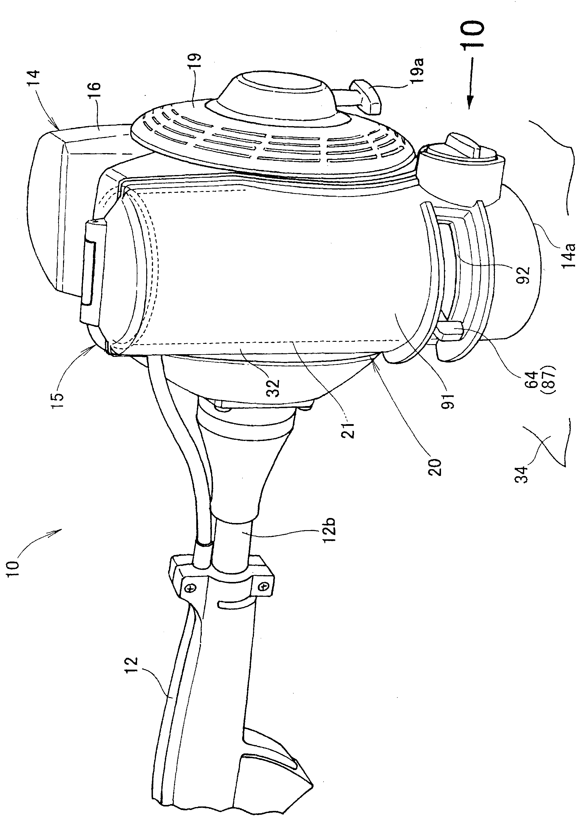
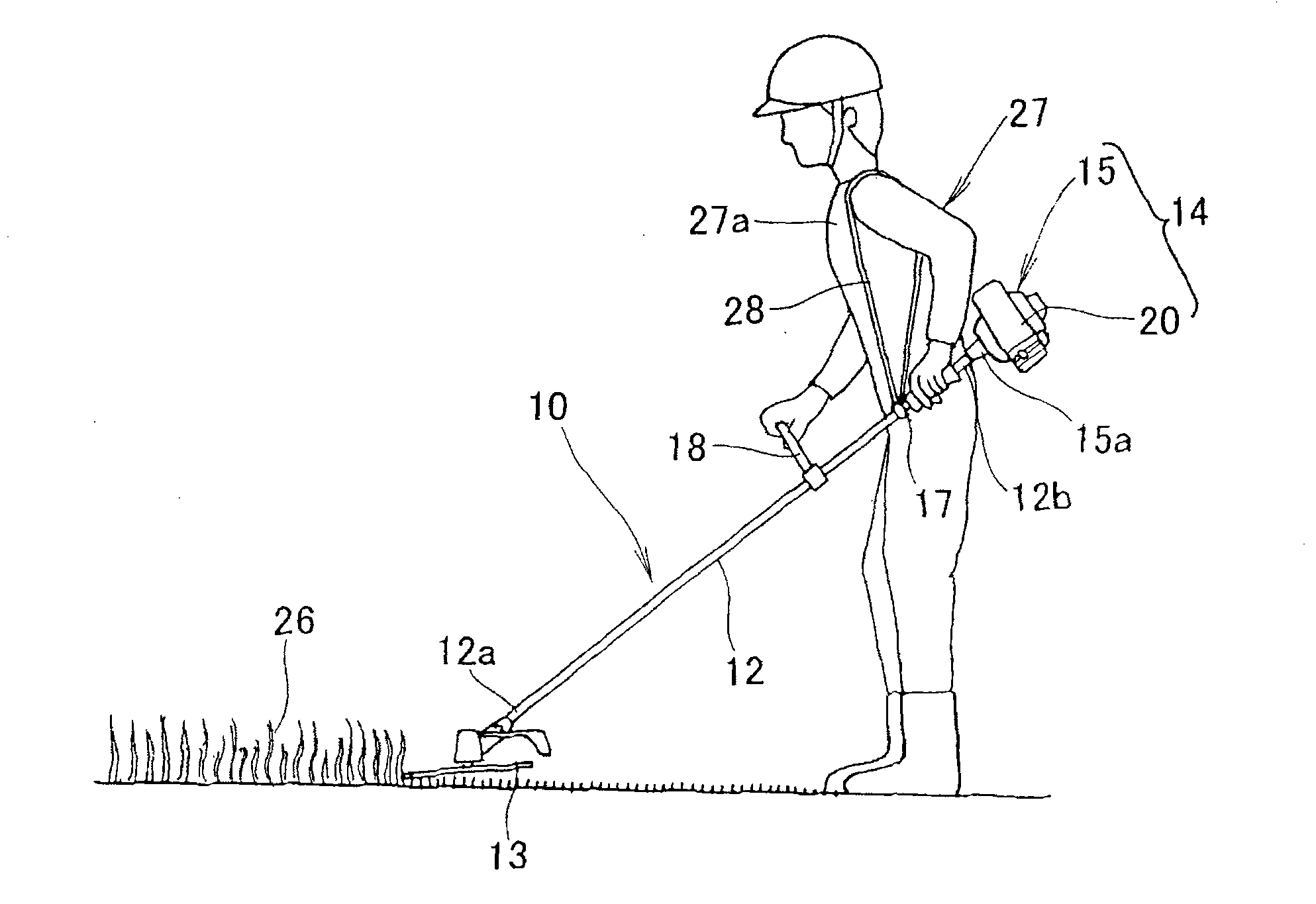
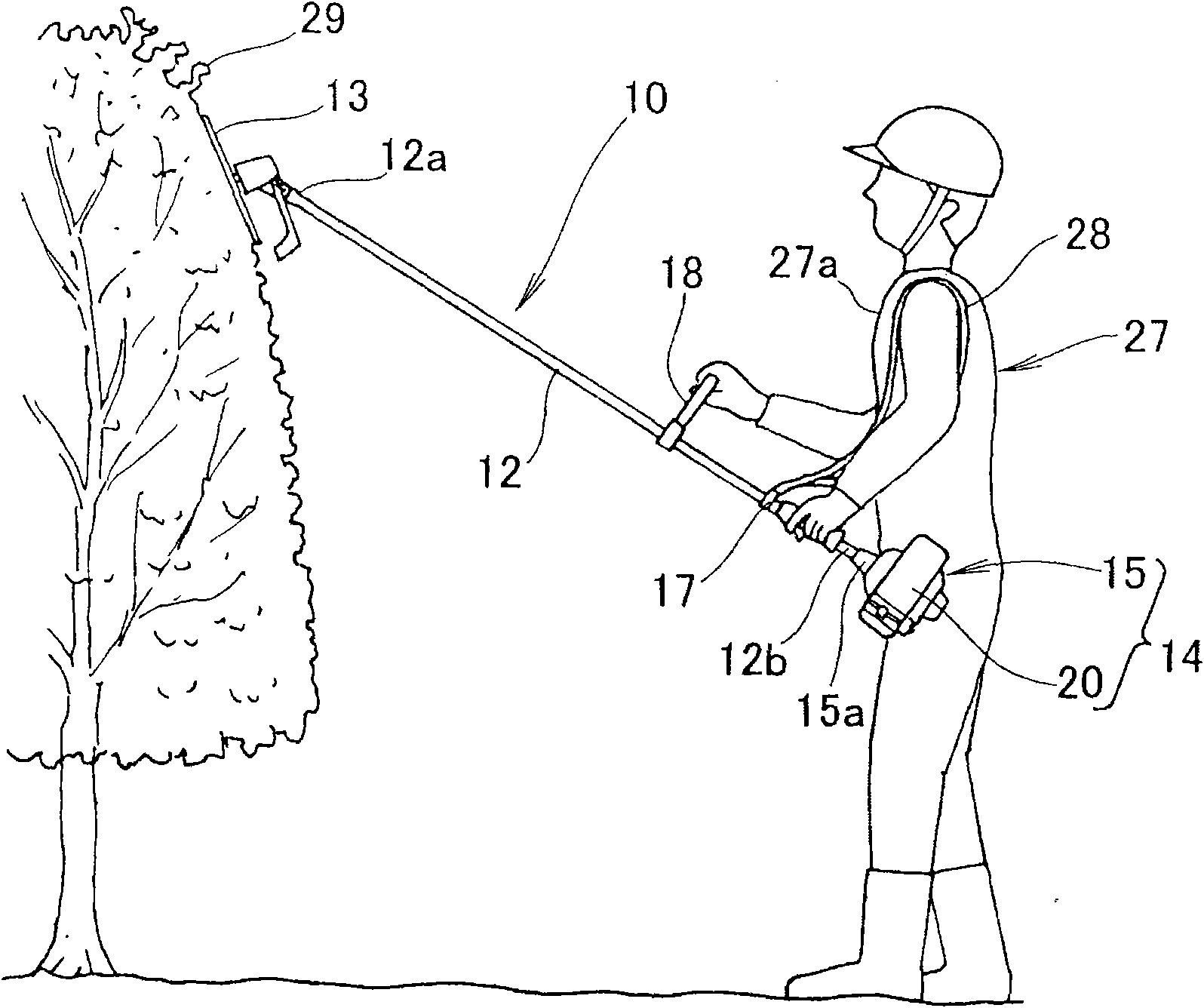
[0038] Such as figure 1 , 2A As shown in and 2B, the bush cutter 10 includes a cutting blade 13 (working attachment) provided at the front end 12a of the working rod 12, a working machine main body provided at the rear end 12b of the working rod 12 and including an engine (gas engine) 15 14. A gas cylinder holding unit 20 integrally formed with the engine compartment 16 of the engine 15, a gas cylinder or a gas cylinder 21 removably held in the gas cylinder holding unit 20, disposed on the working rod 12 and adjacent to the working rod 12 An attachment ring 17 at the rear end 12b of th...


PUM


Abstract

A gas-engine-powered handheld working machine (10) has a working unit driven by an engine capable of running on a gas fuel supplied from a gas cartridge (21). The gas cartridge is arranged such that when the handheld working machine is disposed in a normal rest position where the handheld working machine is placed on a horizontal plane (34) with a bottom surface (14a) of a machine body (14) lyingflat on the horizontal plane, the gas cartridge is disposed in a substantially vertical position with a discharge nozzle (23) directed downwards while a central axis (35) of the gas cartridge extendssubstantially perpendicular to the horizontal plane.

Description

technical field [0001] The present invention relates to a hand-held working machine having a working unit driven by a gas engine capable of running on gas fuel supplied from a gas cylinder. Background technique [0002] A related type of hand-held work machine includes a bush cutter equipped with a power source formed by a gas engine. A typical example of such a gas engine-driven bush cutter is disclosed in Japanese Utility Model Application Publication (JP-U-A) No. 03-116,751. The above-disclosed bush cutter includes a gas cylinder bay associated with the gas engine and configured to hold the gas cylinders in a generally horizontal position. In operation, liquefied gas fuel stored in the gas cylinder is supplied from the discharge nozzle of the gas cylinder to the engine to drive the engine, and the engine rotates a cutting blade as a working unit, thereby performing a desired bush cutting operation. [0003] In the bush cutter shown in JP-U 03-116,751, the gas cylinder i...

Claims


Application Information

Patent Timeline
Patent Type & Authority Applications(China)
IPC IPC(8): F02M21/02A01D34/84A01D34/90
CPCA01M7/0021A01G3/033A01M19/00A01M7/001A01M15/00A01D46/253F02M21/029A01M21/04F02M21/0221Y02T10/32A01G3/06F02B43/00F02M21/0296A01D34/416A01D34/90F02M21/00Y02T10/30A01G3/062F02M21/02A01D34/68A01D34/82
Inventor 古谷健太郎东功一
Owner HONDA MOTOR CO LTD
Why Eureka
Try Eureka