

DC interference test control system
A DC interference and test line technology, which is applied in the field of DC interference testing, can solve problems such as major power grid accidents, substation or power plant shutdown accidents, and no simulation environment has been established, so as to ensure safe operation, huge economic and social benefits, and improve Effect of Immunity to DC Interference
- Summary
- Abstract
- Description
- Claims
- Application Information
AI Technical Summary
Problems solved by technology
Method used
Image

Examples
Embodiment 1
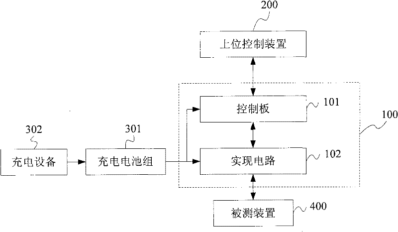
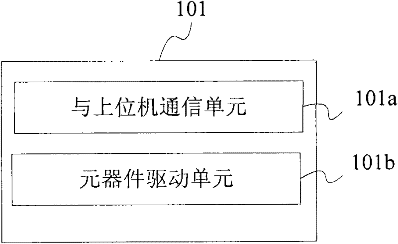
[0024] like figure 1 Shown is the DC interference test control system of the embodiment. The system includes: a DC interference simulation device 100 and a host control device 200 ; the DC interference simulation device 100 includes: a control board 101 and an implementation circuit 102 . The host control device 200 is connected to the DC interference simulation device 100 through an Ethernet port. The battery pack 301 provides power for the DC interference simulation device 100 , and the charging device 302 charges the battery pack 301 . The device under test is connected to the test interface of the DC interference simulation device 100 .
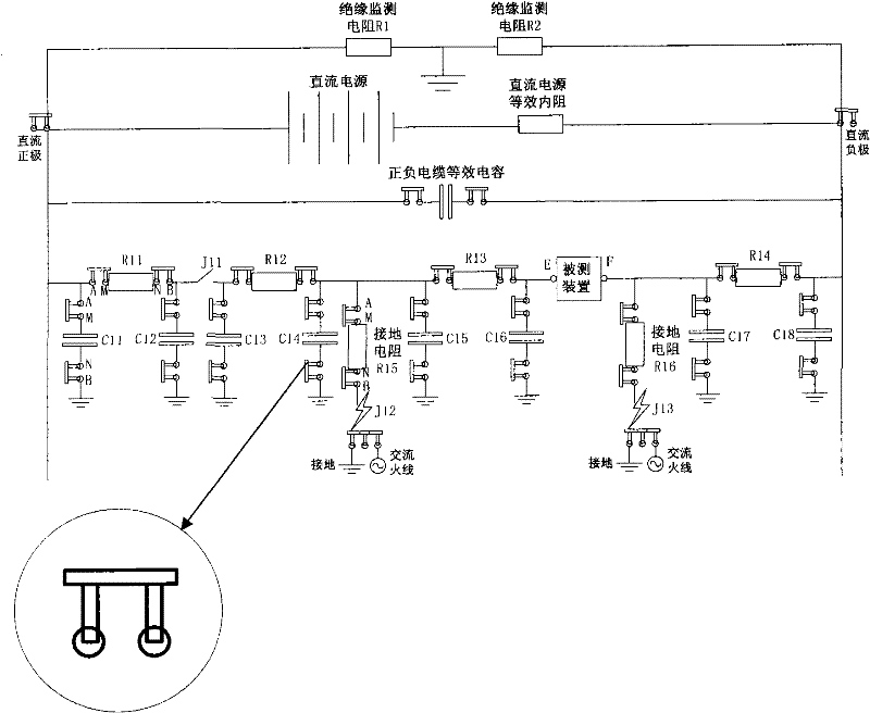
[0025] like figure 2 As shown, the implementation circuit 102 further includes: a DC positive interface, used to connect the positive pole of the external DC power supply; a DC negative pole interface, used to connect the negative pole of the external DC power supply; a positive pole interface of the device under test, used to connect ...
Embodiment 2
[0051] like Figure 8 As shown, the DC interference test system of this embodiment includes: a plurality of DC interference simulation devices (100a, 100b and 100c) and a host computer 200 as a host control device; the DC interference simulation devices (100a, 100b and 100c) are controlled through a network The box 500 is connected to the host computer 200 . Each DC interference simulation device includes: a control board and a realization circuit. The battery pack 301 provides power for the DC interference simulation devices ( 100 a , 100 b and 100 c ), and the charging device 302 charges the battery pack 301 . The devices under test (400a, 400b and 400c) are connected to the test interfaces of the corresponding DC interference simulation devices (100a, 100b and 100c).
[0052] The circuit connection relationship of the DC interference test system with three DC interference simulation devices is as follows: Figure 9 shown. Wherein, the implementation circuit of each DC i...
PUM
 Abstract
Description
Claims
Application Information