A capacitive dc-dc converter
A DC-DC, capacitor technology, applied in the field of DC-DC converters, to achieve the effect of enhanced regulation and protection
- Summary
- Abstract
- Description
- Claims
- Application Information
AI Technical Summary
Problems solved by technology
Method used
Image

Examples
Embodiment Construction
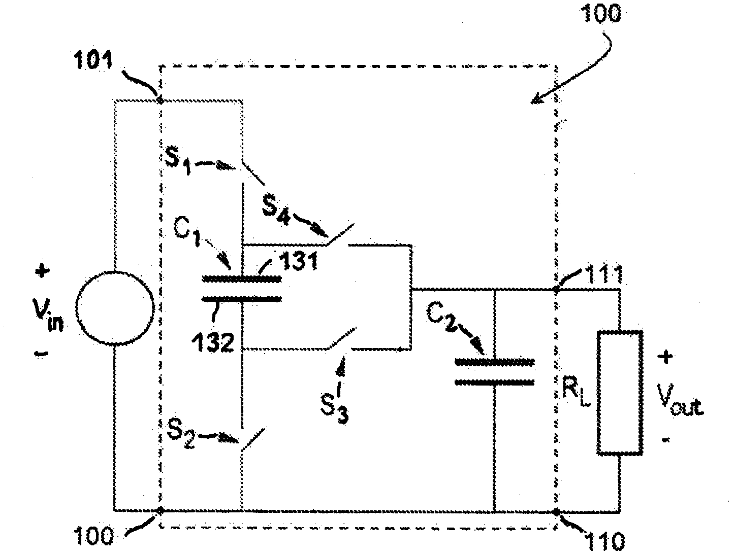
[0038] figure 1 A simple schematic circuit diagram of a capacitive DC-DC converter according to the prior art is depicted. A voltage Vin is applied across the inputs 100, 101, and the load resistor R L Current is drawn through the voltage of outputs 111 , and 110 . Across the inputs 100, 101 via a switch is a charge pump capacitor C1. Switch S1 connects the first electrode 131 of capacitor C1 to the high side 101 of the input and switch S2 connects the second electrode 132 of capacitor C1 to the low side 100 of the input. Switches S4 and S3 respectively connect the first electrode 131 and the second electrode 132 of the charge pump capacitor C1 to the high side 111 of the voltage output. A second capacitor C2 is connected between the high side 111 and the low side 110 of the output.
[0039] In the operation of the capacitive converter, in a first phase, a control unit (not shown) sets all the odd-numbered switches to their conducting state, ie the closed state. That is, ...
PUM
 Abstract
Description
Claims
Application Information
 - R&D
- Intellectual Property
- Life Sciences
- Materials
- Tech Scout
- Unparalleled Data Quality
- Higher Quality Content
- 60% Fewer Hallucinations
Browse by: Latest US Patents, China's latest patents, Technical Efficacy Thesaurus, Application Domain, Technology Topic, Popular Technical Reports.
© 2025 PatSnap. All rights reserved.Legal|Privacy policy|Modern Slavery Act Transparency Statement|Sitemap|About US| Contact US: help@patsnap.com