Multi-way reversing valve

A technology for switching valves and valve cores, which is applied to multi-port valves, valve devices, valve details, etc., can solve the problems of low configuration freedom, large switching valves, and redundant space, so as to reduce assembly and processing costs, simplify the structure, and realize Effects of configuring degrees of freedom

Active Publication Date: 2011-10-12
FUJIKOKI MFG CO LTD
View PDF11 Cites 4 Cited by
  • Summary
  • Abstract
  • Description
  • Claims
  • Application Information

AI Technical Summary

Problems solved by technology

Therefore, in order to switch the flow path, it is required to increase (diameter of) the valve seat portion 65 (nearly twice the radius of rotation of the switching valve core portion 50B). The side opposite to the (open) side where the ports 12, 13 are located creates excess space ( Figure 5 In the part indicated by S), there is a problem that the switching valve 10' is relatively large
[0026] In addition, in the above structure, the fluid introduction port 11 has to be arranged on the rotation axis O of the driver, and there is also a problem that the degree of freedom in the arrangement of the ports 11, 12, 13, 14, etc. is low.

Method used


Image

  • Multi-way reversing valve
  • Multi-way reversing valve
  • Multi-way reversing valve

Examples


Embodiment Construction

[0065] Hereinafter, embodiments of the multi-directional switching valve of the present invention will be described with reference to the drawings.

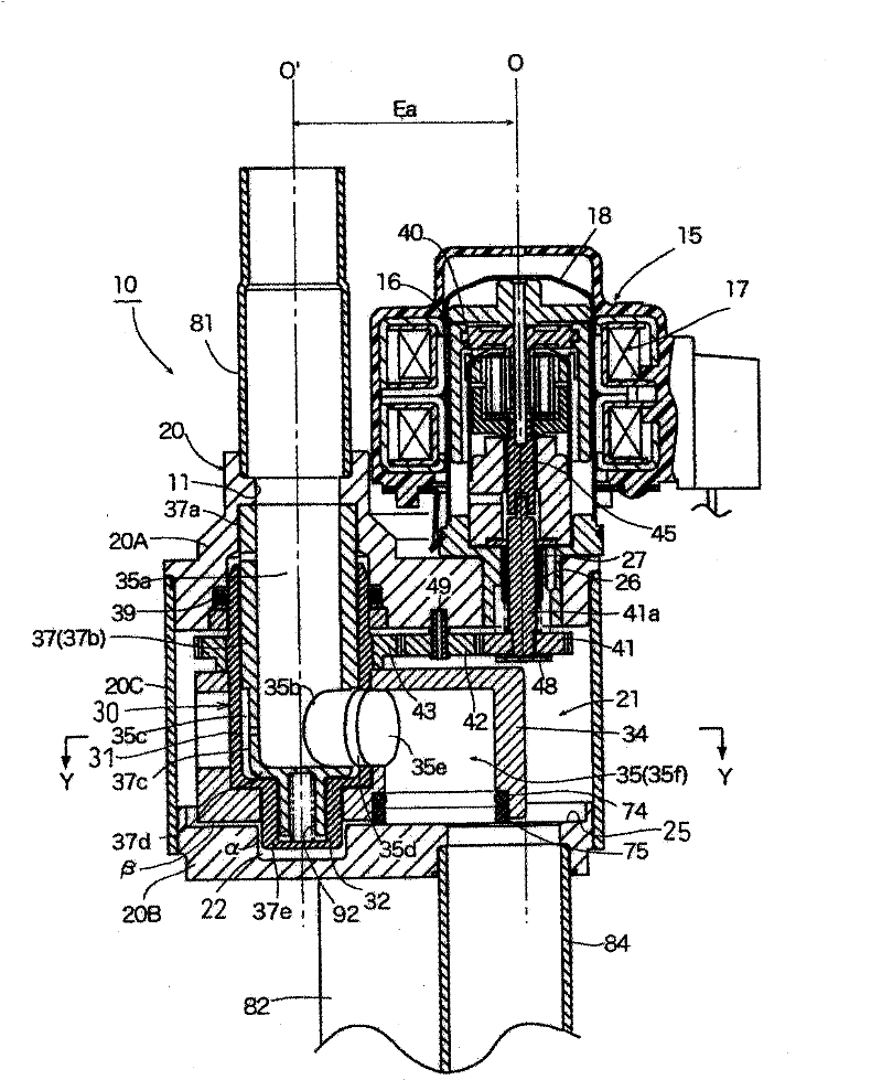
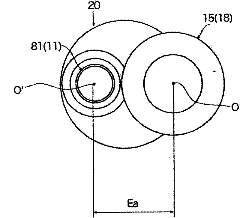
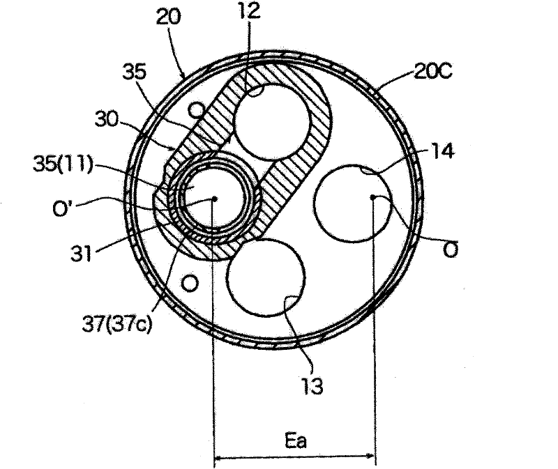
[0066] figure 1 It is a longitudinal sectional view showing one embodiment of the multi-way switching valve according to the present invention, figure 2 yes figure 1 The top view of the multi-way switching valve shown, image 3 From figure 1 The cross-sectional view viewed in the direction of the Y-Y arrow. In each figure, with the aforementioned Figure 4 , Figure 5 The parts corresponding to the parts of the multi-way switching valve 10' shown in the figure are marked with the same symbols, and the description thereof will be omitted.

[0067] The multi-way switching valve 10 of figure example, and Figure 4 , Figure 5 The multi-way switching valve shown in is the same, it has a high-pressure fluid inlet port 11, a first fluid inlet and outlet port 12, a second fluid inlet and outlet port 13, and a low-pressure flui...


PUM


Abstract

The present invention provides a multi-way reversing valve that allows for a reduction in size, an improvement in layout freedom, a reduction in assembly processing costs, etc. The multi-way reversing valve includes a valve housing having a valve seat part in which a plurality of fluid in / out ports are formed; a valve member adapted to be rotated; and an actuator adapted to rotationally actuate the valve member. A fluid inlet port and / or a fluid outlet port is / are formed in the valve housing. A passage adapted to selectively place the fluid inlet port or the fluid outlet port in communication with the plurality of fluid in / out ports is formed within the valve member. Flow paths are reversed by rotating the valve member to selectively place the fluid inlet port or the fluid outlet port in communication with one of the plurality of in / out ports via the passage. The rotational axis line O' of the valve member is laterally eccentric relative to the rotational axis line O of an output shaft of the actuator by a predetermined distance Ea.

Description

technical field [0001] The present invention relates to multi-way switching valves such as three-way switching valves and four-way switching valves used in refrigeration cycles (heat pumps), and more particularly to rotary multi-way switching valves that use drivers such as motors to rotate valve cores to switch flow paths . Background technique [0002] As this multi-way switching valve, the applicant of the present application has proposed such as Figure 4 The technical solution of the shown multi-directional switching valve (refer to patent documents 1, 2, etc.). Hereinafter, the illustrated multi-directional switching valve will be briefly described. exist Figure 4 In , in order to help understanding, the first fluid inlet and outlet port 12 and the second fluid inlet and outlet port 13 are drawn on the left and right sides of the central axis 0, actually based on Figure 5 shown in the configuration to set up. [0003] The multi-way switching valve 10' shown in the...

Claims


Application Information

Patent Timeline
IPC IPC(8): F16K11/074F16K31/02
CPCF16K11/074Y10T137/86493Y10T137/86839F16K31/041F16K31/53F25B41/26F16K27/0263
Inventor 神尾猛
Owner FUJIKOKI MFG CO LTD
Why Eureka
Try Eureka