Electronic expansion valve

A technology for electronic expansion valves and rotors, applied in valve details, valve devices, valve operation/release devices, etc., can solve problems such as stuck, increase the difficulty of parts assembly, increase product costs, etc., to achieve the reduction of longitudinal length, manufacturing Effects of low cost and improved reliability

Active Publication Date: 2011-10-12
SHANGHAI JUNLE REFRIGERATION CONTROL
View PDF5 Cites 16 Cited by
  • Summary
  • Abstract
  • Description
  • Claims
  • Application Information

AI Technical Summary

Problems solved by technology

However, this kind of electronic expansion valve mainly has the following disadvantages: (1) Its limit mechanism adopts a stopper assembly, and the stopper rod used results in a large radial dimension of the stopper assembly structure, which affects the overall height of the valve body, and due to processing Accuracy is affected, and it is easy to cause jamming and other situations; (2) the number of internal parts of the valve body is large, and the structure is complex, which increases the difficulty of parts assembly and will inevitably increase the cost of the product

Method used


Image

  • Electronic expansion valve
  • Electronic expansion valve
  • Electronic expansion valve

Examples


Embodiment Construction

[0017] In order to make the purpose, technical solutions and advantages of the embodiments of the present invention clearer, the technical solutions in the embodiments of the present invention will be clearly and completely described below in conjunction with the drawings in the embodiments of the present invention. Obviously, the described embodiments It is a part of embodiments of the present invention, but not all embodiments.

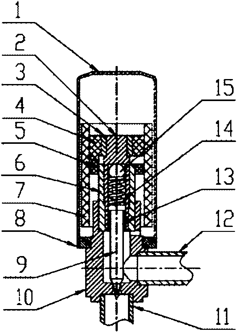
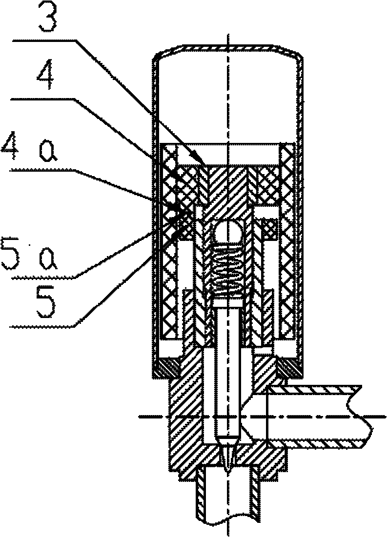
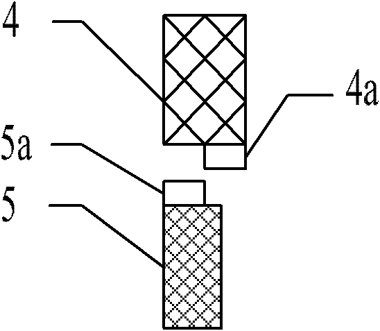
[0018] Such as figure 1 As shown, an electronic expansion valve mainly includes a sleeve 1, a screw sleeve 6, connecting pipes 11 and 12, a valve body 10, and a rotor composed of a multi-pole magnetic ring 7 inside the sleeve 1, bolts 2, and a valve needle 9. Such as figure 2 As shown, the bolt collar 3 and the upper positioning block 4 made of resin material are formed by integral injection molding and fixed connection, and at the same time, a block-shaped protrusion 4a with a position-limiting effect is formed under the upper positioning block 4...


PUM


Abstract

The invention provides an electronic expansion valve. The spinning position of a screw thread is restricted through using a lump protrusion with a limit function; the pretension to a valve port by a valve needle is controlled; a rotor part is designed into a split structure; after the relative position of the valve needle and a valve body is regulated well, a rotor component and a bolt are fixed together in a tight matching or welding mode; then the outer screw thread of the bolt fixed on the rotor and the inner screw thread of a screw sleeve are matched, the rotor can move up and down under the guidance of the screw thread when the rotor rotates, the relative movement of the valve needle and the valve port of the valve body is controlled, thus the flow rate of a refrigerant is controlled. Compared with the existing structure, the electronic expansion valve provided by the invention has the advantages that a stop rod component of a greater size is prevented from being used, the radial size of the valve body is reduced, also the number of components is reduced, the structure is simplified, the assembling is easy, and the volume is small.

Description

technical field [0001] The invention relates to valve technology, in particular to an electronic expansion valve, which is used in air conditioning, refrigeration and other fields to control the flow of refrigerant. Background technique [0002] At present, the electronic expansion valve uses the working principle of the stepping motor, uses the coil to drive the rotation of the magnetic rotor part, and converts the rotation of the magnetic rotor part into the up and down movement of the screw, and the screw drives the valve needle connected to it to rise or fall. , so as to control the flow rate of the electronic expansion valve. The invention patent with the authorized publication number CN1789768A represents this common technical solution. Its main structure includes a sleeve, a valve seat, a nut, a screw, a stopper assembly, and a magnetic rotor. A valve cavity and a valve body cavity are formed; the magnetic rotor is set in the valve cavity, and is connected with one e...

Claims


Application Information

Patent Timeline
Patent Type & Authority Applications(China)
IPC IPC(8): F25B41/06F16K31/04F16K31/50
CPCY02B30/70
Inventor 冯志军陈成
Owner SHANGHAI JUNLE REFRIGERATION CONTROL
Why Eureka
Try Eureka