Quasi-distributed white light interference strain sensing system based on optical fiber full-spectrum reflectors with adjustable splitting ratios
A white light interference and strain sensing technology, which is applied in the direction of optical devices, measuring devices, instruments, etc., can solve the problems of complex production of fiber optic full-spectrum mirrors, difficulty in realizing fine control of splitting ratio, and difficulty in engineering use, etc., and achieve good results. Control, structural stability, suitable for engineering effects
- Summary
- Abstract
- Description
- Claims
- Application Information
AI Technical Summary
Problems solved by technology
Method used
Image
Examples
Embodiment 1
[0034] Example 1: Deformation measurement of a single white light interference sensor based on an adjustable split ratio fiber optic full-spectrum mirror
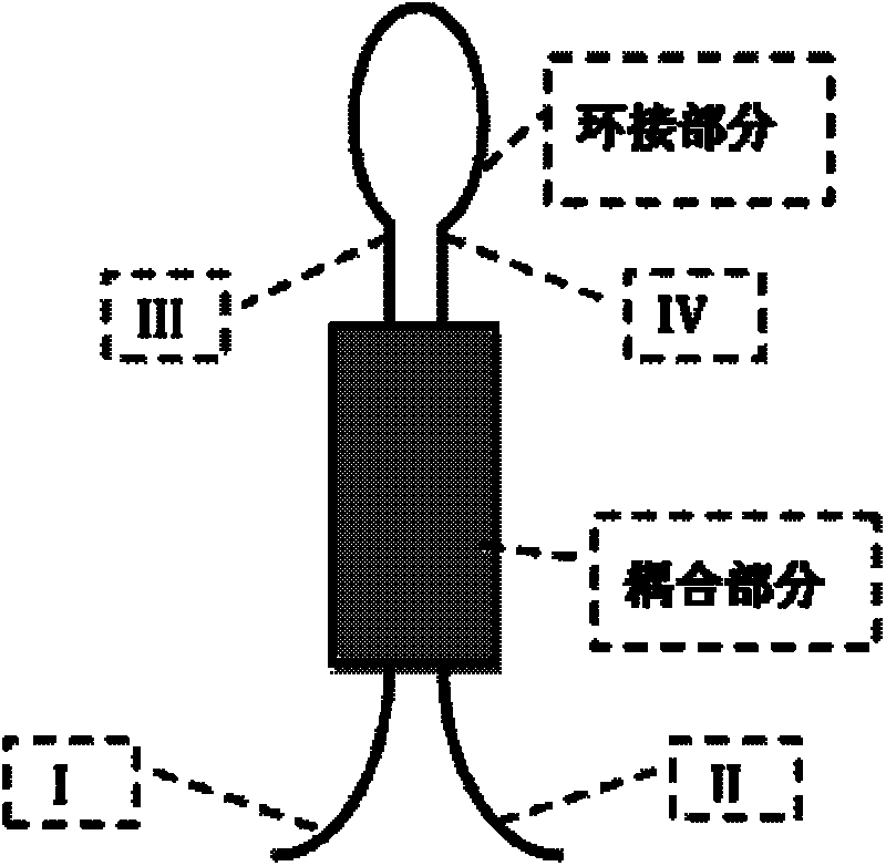
[0035] Based on the adjustable splitting ratio fiber full-spectrum reflector: In this adjustable splitting ratio based fiber full-spectrum reflector, a fiber-optic full-spectrum reflector composed of a 2×2 fiber coupler with a splitting ratio of a:b is as follows: figure 2 shown. Because the splitting ratio of the fiber coupler is determined according to the incident fiber terminal, that is to say, the sub-terminal with the splitting ratio a is on the same side as the terminal of the incident light. That is, the incident light intensity I from terminal I A , then the light intensity obtained at the III end is aI A ; And when the same light intensity is incident from the incident terminal II end, the light intensity obtained at the IV end is aI A . In this way: when the incident light enters the 2×2 coupler from the I e...
Embodiment 2
[0046] Example 2: Distributed white light interferometry system based on fiber optic full-spectrum reflector with adjustable splitting ratio
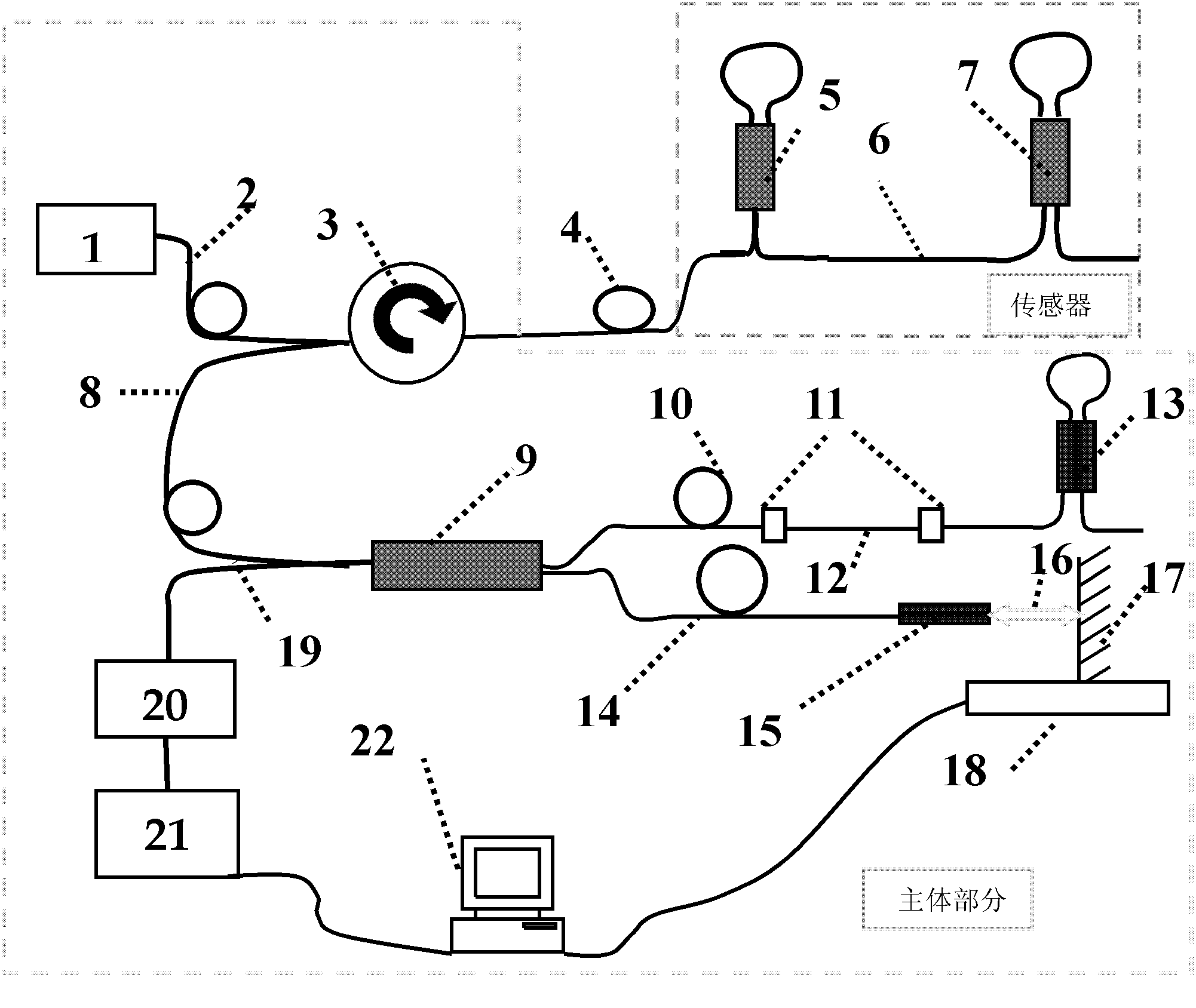
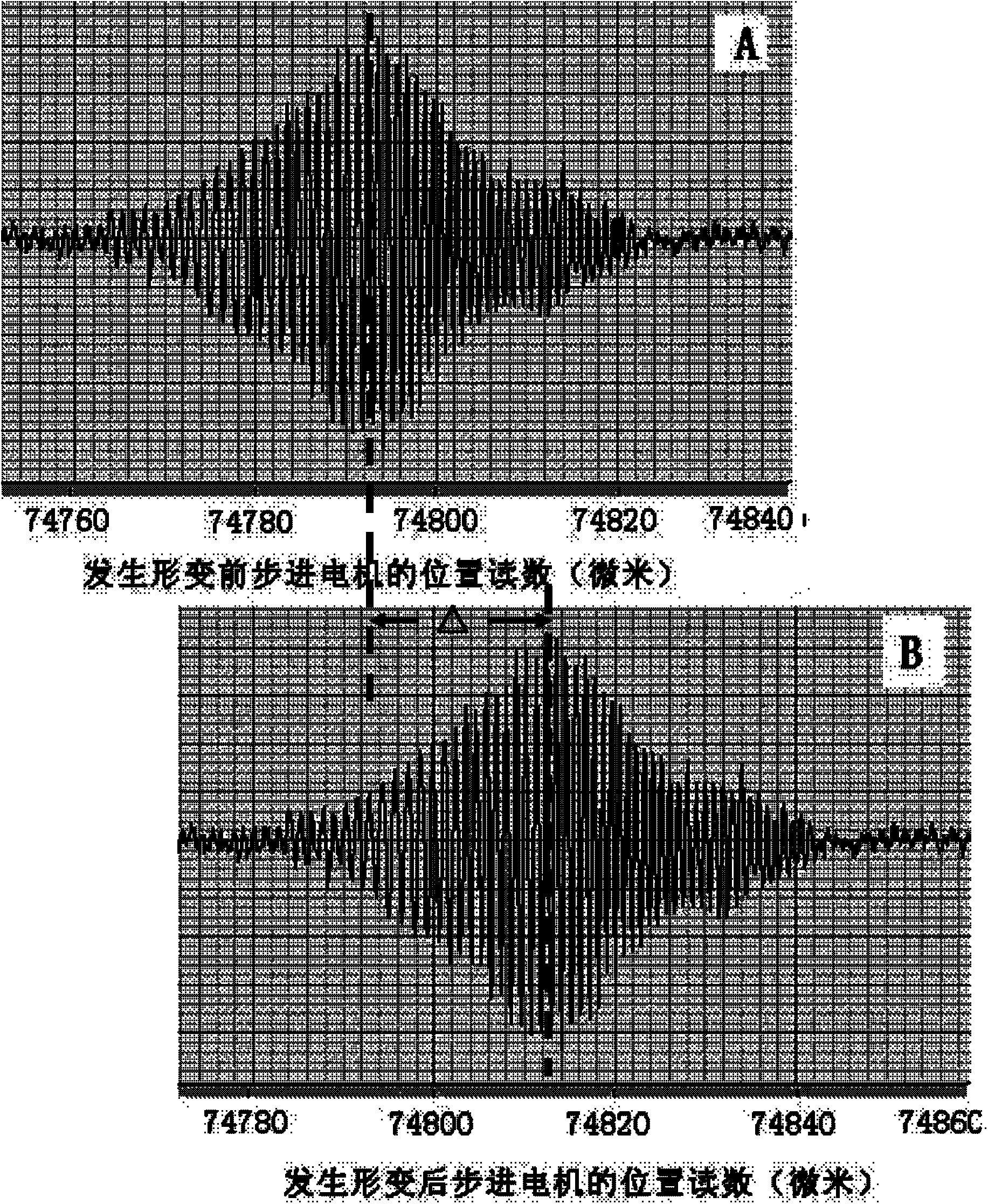
[0047] like Figure 5 Shown: In the case of cascading multiple sensors, the length of the matching optical fiber of the fixed reference arm is equal to the longest sensing optical fiber length of the sensor, and the equal optical path of other sensors can be obtained by adjusting the length of the blank optical path of the adjustable reference arm output. The interferogram for each sensor initial type variable is shown below the figure. When the sensor experiences strain, the positions of these interferograms are as figure 1 The same principle as given the corresponding sensor type variables.
PUM
 Abstract
Description
Claims
Application Information
 - R&D
- Intellectual Property
- Life Sciences
- Materials
- Tech Scout
- Unparalleled Data Quality
- Higher Quality Content
- 60% Fewer Hallucinations
Browse by: Latest US Patents, China's latest patents, Technical Efficacy Thesaurus, Application Domain, Technology Topic, Popular Technical Reports.
© 2025 PatSnap. All rights reserved.Legal|Privacy policy|Modern Slavery Act Transparency Statement|Sitemap|About US| Contact US: help@patsnap.com


