Hydraulic compression gauge sealing rotation structure

A technology of rotating structure and hydraulic pressure, applied in the field of hydraulic machinery, can solve the problems of easy operation errors, easy damage, and inability for operators to operate, so as to achieve the effect of not easy operation errors and easy damage.

Inactive Publication Date: 2011-10-19
赵瑶志
View PDF0 Cites 2 Cited by
  • Summary
  • Abstract
  • Description
  • Claims
  • Application Information

AI Technical Summary

Problems solved by technology

[0003] The purpose of the present invention is to provide a hydraulic pressure gauge sealing and rotating structure to overcome the defect that the existing hydraulic pressure gauge is easily damaged due to the influence of vibration; at the same time, it is also to overcome the existing hydraulic pressure gauge. The same, the operator cannot operate in different parts of the hydraulic machinery, which brings some inconvenience to the observation, is prone to operating errors, and causes defects of corresponding consequences

Method used


Image

  • Hydraulic compression gauge sealing rotation structure
  • Hydraulic compression gauge sealing rotation structure

Examples


Embodiment Construction

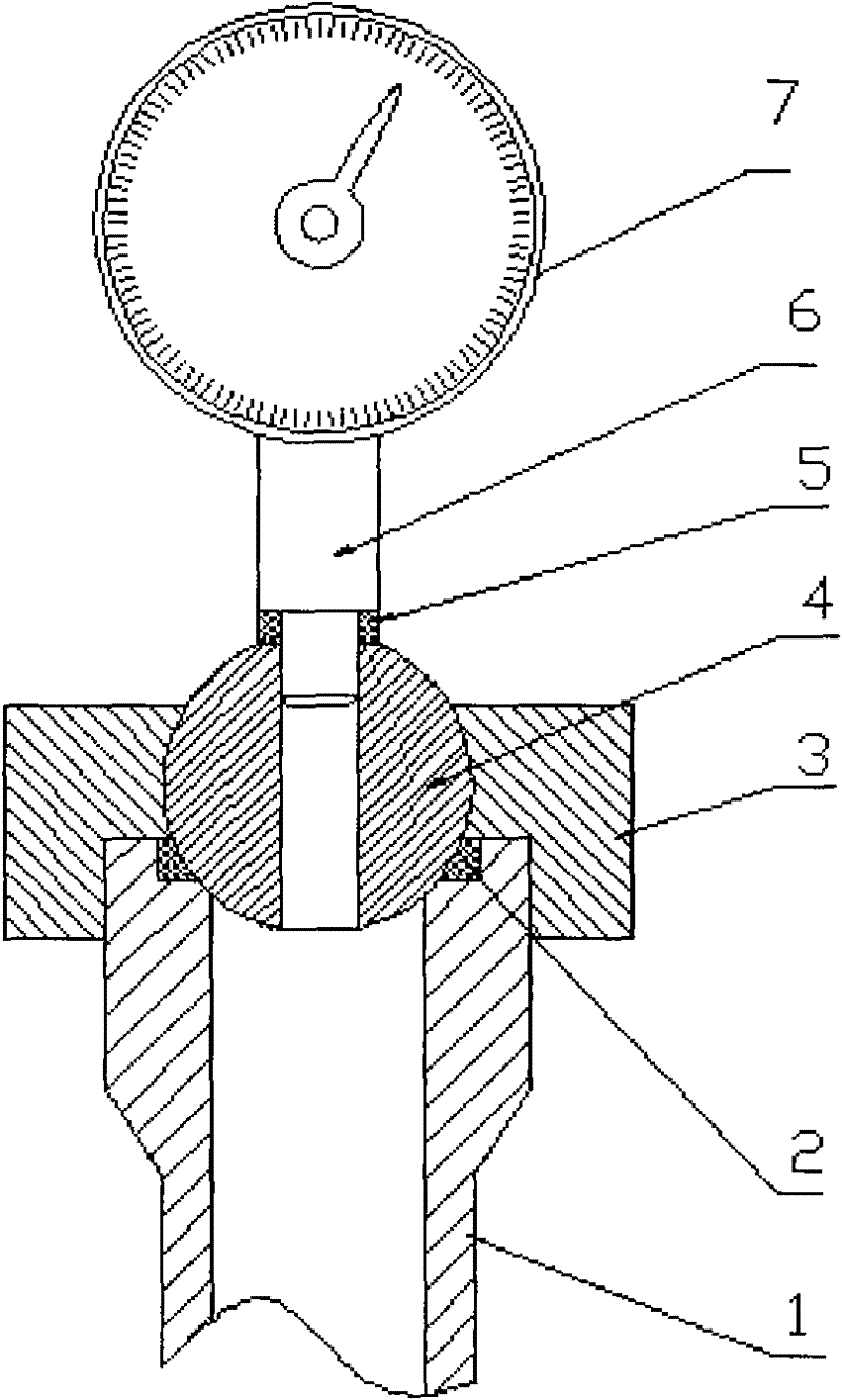
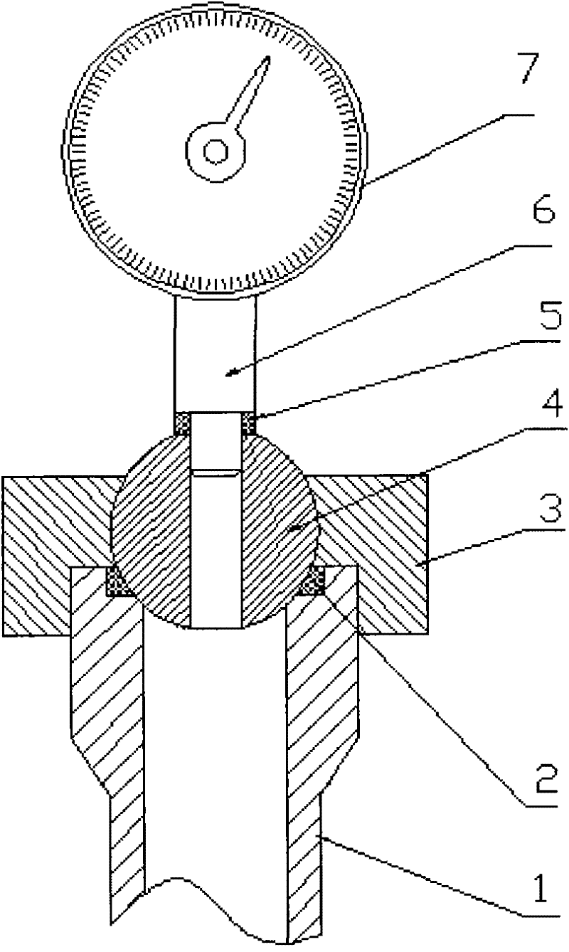
[0009] Install and fix the fixed pipe (1) with the fuselage of the hydraulic machine or the hydraulic station, and place the sealing ring (2) on the upper mouth of the fixed pipe (1) and place the ball joint (4) on the fixed On the upper part of the pipe (1), fix the ball joint (4) on the upper part of the fixed pipe (1) with the connection head (3), and install the ring sealing ring (5) on the joint part of the pressure pipe (6) , and the pressure pipe (6) is connected and fixed with the ball joint (4) by threaded connection.


PUM


Abstract

Provided is a hydraulic compression gauge sealing rotation structure which is that a fix pipe and the body or hydraulic station of a hydraulic machine are fixed and installed. A sealing ring is placed at the upper opening part of the fix pipe and a spherical joint is placed on the upper opening part of the fix pipe. A joint is used to fix the spherical joint on the upper opening part of the fix pipe. An annular sealing ring is provided on the joint position of a manometer tube and the manometer tube and the spherical joint are connected and fixed through a screw thread connection method.

Description

technical field [0001] The invention relates to a hydraulic pressure gauge structure, in particular to a hydraulic pressure gauge sealing and rotating structure, which belongs to the technical field of hydraulic machinery. Background technique [0002] On the fuselage or hydraulic station of hydraulic machinery, a certain number of hydraulic pressure gauges are generally installed and fixed. The connections between these pressure gauges and the fuselage or hydraulic station are fixed connection structures. Huge vibration will be generated, so the hydraulic gauge is easy to be damaged. At the same time, during the work process, sometimes the operator needs to operate in different parts of the hydraulic machine. Since the installation of the pressure gauge is fixed, this brings a lot of problems to the observation. Certain inconvenience, therefore, prone to operating errors, resulting in corresponding consequences. Contents of the invention [0003] The purpose of the prese...

Claims


Application Information

Patent Timeline
Patent Type & Authority Applications(China)
IPC IPC(8): G01L19/06
Inventor 赵瑶志
Owner 赵瑶志
Why Eureka
Try Eureka