Flow control method and equipment based on link status

A flow control and link state technology, applied in the field of communication, can solve the problems of increasing link congestion, occupying bandwidth, wasting network bandwidth, etc., and achieve the effect of reducing invalid flow, avoiding occupying bandwidth, and improving forwarding performance

Active Publication Date: 2011-10-19
XINHUASAN INFORMATION TECH CO LTD
View PDF4 Cites 16 Cited by
  • Summary
  • Abstract
  • Description
  • Claims
  • Application Information

AI Technical Summary

Problems solved by technology

[0009] The above-mentioned defects for MSTP processing are: (1) In a network with loops, current MSTP eliminates loops by blocking ports. The opposite end of the link where the blocked port is located does not know that the other end is in a blocked state, resulting in some invalid traffic occupies bandwidth on the link
Take the link between Port 1 of Switch A and Port 1 of Switch B as an example. In instance 0, the blocked port is Port 1 of Switch B, but Port 1 of Switch A at the opposite end of the link is forwarding (this state Indicates that the port can forward user traffic) status; suppose that when Switch A receives a broadcast packet of VLAN 2, it needs to broadcast and forward the packet on the port of VLAN 2; since Port 1 allows VLAN 2 to pass through, and the state is Forwarding, Therefore, Switch A needs to copy a copy of the message to Port 1 and forward it. When the message reaches Port 1 of Switch B, the state of the port on instance 0 is Discarding (this state indicates that the port cannot forward the user traffic), so the packet is discarded
From the above process, it can be seen that the transmission of this VLAN 2 packet in this link is meaningless, which wastes network bandwidth.
[0010] (2) Invalid traffic wastes the workload forwarded by the device
[0012] The disadvantages of the above-mentioned Smart Link and RRPP processing are the same as the above-mentioned disadvantages of MSTP, that is, the port does not know the forwarding status of the peer end of the link, resulting in some invalid traffic being forwarded to the link, increasing the possibility of link congestion sex

Method used


Image

  • Flow control method and equipment based on link status
  • Flow control method and equipment based on link status
  • Flow control method and equipment based on link status

Examples


Embodiment Construction

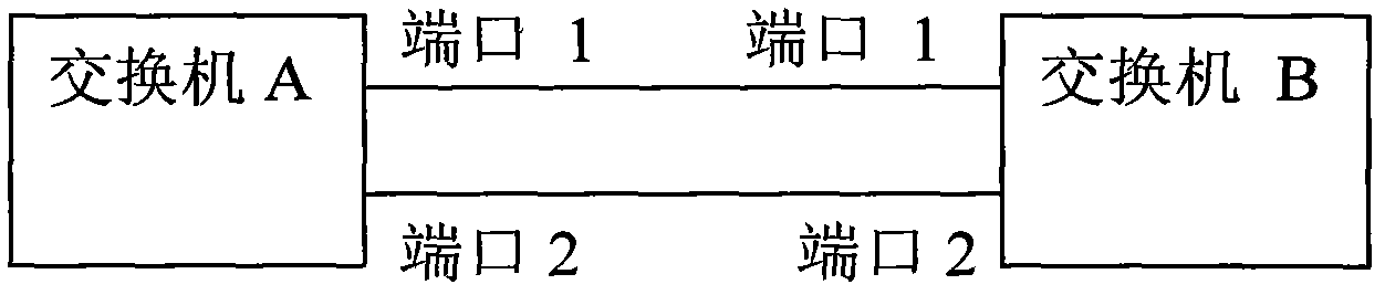
[0038] The present invention proposes a link state-based flow control method, which is applied to a system including a sending end and a receiving end, and a point-to-point link is formed between the first port of the sending end and the second port of the receiving end. Among them, the sending end and the receiving end are relative, with figure 2 Refer to the schematic diagram of the network model for the present invention, then when switch A is the sending end, port 1 is the first port, switch B is the receiving end, and port 2 is the second port; when switch B is the sending end, port 2 is the first port port, switch A is the receiving end, and port 1 is the second port.

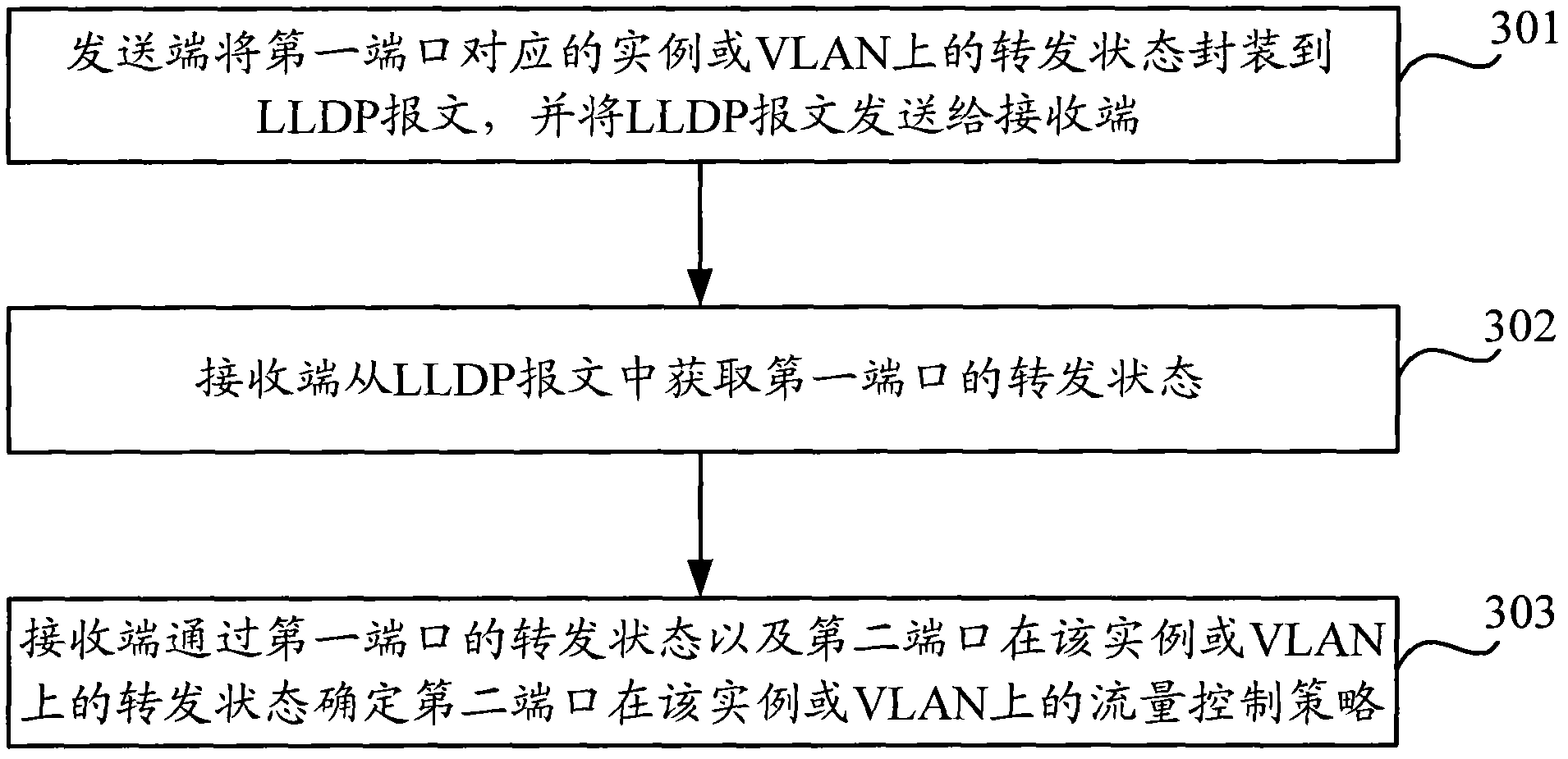
[0039] Such as image 3 As shown, the link state-based flow control method includes the following steps:

[0040] In step 301, the sending end encapsulates the forwarding status of the instance corresponding to the first port or the VLAN into an LLDP message, and sends the LLDP message to the receiving...


PUM


Abstract

The invention discloses a flow control method and equipment based on the link status. The method comprises the following steps that a transmitting terminal packages transmitting status of a first port in an example or a VLAN (Virtual Local Area Network) into an LLDP (Link Layer Discovery Protocol) message, and transmits the LLDP message into a receiving terminal; and the receiving terminal acquires the transmitting status of the first port from the LLDP message, and determines a flow control strategy through the transmitting status of the first port. In the invention, invalid flow in a point-to-point link can be reduced, and the invalid flow can be prevented from occupying bandwidth.

Description

technical field [0001] The present invention relates to the field of communication technology, in particular to a link state-based flow control method and equipment. Background technique [0002] The current technologies to solve the problem of Layer 2 network loops include STP (Spanning Tree Protocol, Spanning Tree Protocol), RSTP (Rapid Spanning Tree Protocol, Rapid Spanning Tree Protocol), MSTP (Multiple Spanning Tree Protocol, Multi-Instance Spanning Tree Protocol), PVST (Per-VLAN Spanning Tree, each VLAN (Virtual Local Area Network, virtual local area network) spanning tree) and other spanning tree protocols and RRPP (Rapid Ring Protection Protocol, fast ring protection protocol). [0003] PVST and MSTP can calculate the forwarding status of ports according to different VLANs; STP and RSTP do not support multiple instances, and cannot calculate the forwarding status of ports according to different VLANs; / RSTP / MSTP / PVST have faster convergence speed, and RRPP networkin...

Claims


Application Information

Patent Timeline
Patent Type & Authority Applications(China)
IPC IPC(8): H04L12/56H04L12/46H04L47/20
CPCY02D30/00
Inventor 王佳炳吴玲
Owner XINHUASAN INFORMATION TECH CO LTD
Why Eureka
Try Eureka