Motorized power steering device

A power steering device, electric technology, applied in the direction of power steering mechanism, electric steering mechanism, transmission parts, etc., can solve the driver's uncomfortable and unpleasant problems, so as to prevent discomfort, ensure steering feeling, smooth and comfortable The effect of steering feel

Active Publication Date: 2011-10-19
NSK LTD
View PDF11 Cites 4 Cited by
  • Summary
  • Abstract
  • Description
  • Claims
  • Application Information

AI Technical Summary

Problems solved by technology

And, with the stick-slip between such peripheral surfaces, vibrations and abnormal noises such as "beeps" may be generated, which may give the driver an uncomfortable and unpleasant feeling.

Method used


Image

  • Motorized power steering device
  • Motorized power steering device
  • Motorized power steering device

Examples


Embodiment Construction

[0047] [the first example of embodiment]

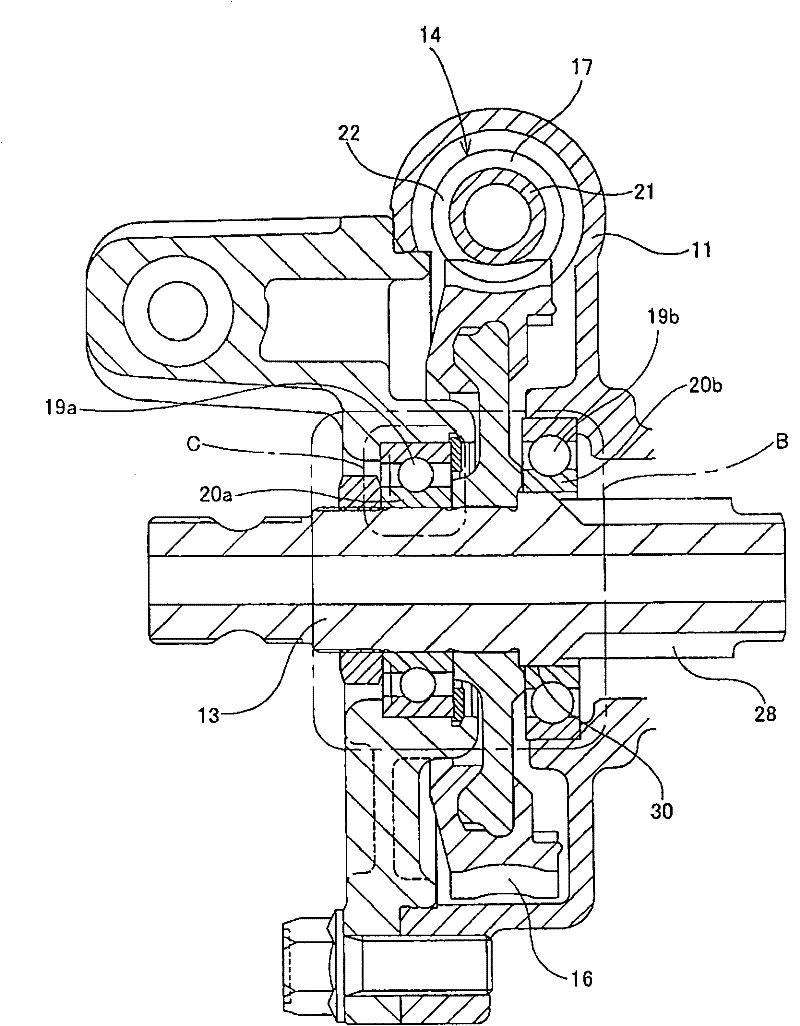
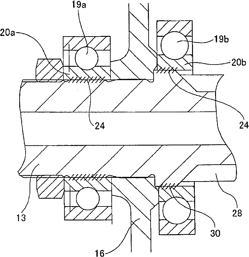
[0048] Figure 1~2 The first example of the embodiment of the present invention is shown. Among them, the electric power steering device of this example is characterized in that it has the output shaft 13 corresponding to the rotating shaft of the present invention and the inner rings 20a, 20b of a pair of rolling bearings 19a, 19b supporting the output shaft 13. A structure in which stick-slip is unlikely to occur. In addition, the overall structure and function of the electric power steering Figure 11 The conventional structure shown, Figures 12 to 14 The shown structures are the same, so illustration and description of parts equivalent to the above-mentioned structures are omitted or simplified, and the following description will focus on the characteristic parts of this example.

[0049] The situation in this case is also the same as Figures 12 to 13 The illustrated structure is the same, and the output shaft 13 is rotatab...


PUM


Abstract

Provided is a motorized power steering device which is equipped with a structure wherein it is possible to prevent the occurrence of stick-slip between the outer peripheral surface of a rotation shaft (13) and the inner peripheral surfaces of the inner races (20a, 20b) of anti-friction bearings (19a, 19b). For this purpose, lubricant (24) or an elastic member (25) is interposed between the outer peripheral surface of the rotation shaft (13) and the inner peripheral surface of at least either one of the inner races (20a, 20b). In a case where the lubricant (24) is to be additionally interposed on the rotation shaft (13), the pertinent portion is provided with recessed surfaces which hold the lubricant (24).

Description

technical field [0001] The present invention relates to an electric power steering device. The electric power steering device is assembled in a steering device of an automobile and uses an electric motor as auxiliary power, thereby reducing the force required for the driver to operate the steering wheel. Background technique [0002] The steering device of the car through such as Figure 10 In the shown configuration, the movement of the steering wheel 1 is transmitted to the steering transmission unit 2 . The motion of the steering wheel 1 is transmitted to the input shaft 6 of the steering transmission unit 2 via the steering shaft 3 , the universal joint 4 a, the intermediate shaft 5 and the universal joint 4 b. As a result, the steering transmission unit 2 pushes and pulls the pair of left and right tie rods 7 so that the steered wheels have a desired steering angle. In addition, in Figure 10 In the illustrated structure, an electric power steering apparatus is install...

Claims


Application Information

Patent Timeline
Patent Type & Authority Applications(China)
IPC IPC(8): B62D5/04F16C19/06F16C19/26F16C23/08F16C33/66F16C35/073
CPCB62D1/16B62D5/0409F16C19/06F16C19/52F16C19/54F16C27/066F16C35/063F16C35/073F16C2326/24F16C2361/61F16H57/0471F16H57/0498
Inventor 相泽寿幸山本武士
Owner NSK LTD
Why Eureka
Try Eureka