Grinding device

A grinding device and dynamic grinding technology, which is applied to beverage preparation devices, kitchen utensils, household utensils, etc., can solve the problems of oversized, easily stuck materials, and materials that are not smooth enough

Inactive Publication Date: 2011-10-26
MIDEA GRP CO LTD
View PDF3 Cites 5 Cited by
  • Summary
  • Abstract
  • Description
  • Claims
  • Application Information

AI Technical Summary

Problems solved by technology

However, there are two problems in this structure. One is that the distance between the movable grinding wheel and the static grinding wheel is fixed. When encountering larger particles of material, it is easy to get stuck, and as the grinding progresses, the material becomes smaller. At this time, the moving grinding wheel and the static grinding wheel The gap of the static grinding wheel is too large to fully grind; the second is that the power of the slurry discharged from the grinding mechanism is insufficient, and the slurry is discharged only by the centrifugal force generated by the rotation of the moving grinding wheel, and the discharge speed is slow, and it is easy to cause part of the slurry to remain at the bottom of the inner grinding wheel , cannot be completely discharged, resulting in part of the material remaining at the bottom of the grinding mechanism, insufficient grinding
In summary, the existing technology results in that the material is not ground fine enough, the material is not smooth enough, and the material is easy to get stuck

Method used


Image

  • Grinding device
  • Grinding device
  • Grinding device

Examples


Embodiment 1

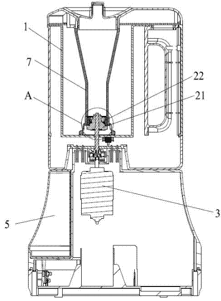
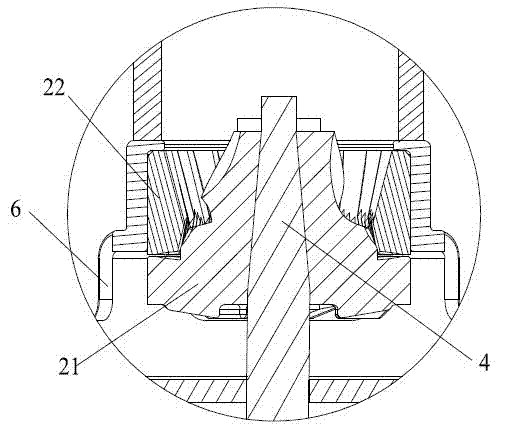
[0027] Such as figure 1 Shown is a schematic structural diagram of the grinding device of this embodiment, including a container 1 and a base 5, and the container 1 is provided with an upper cover. In order to facilitate the cleaning of the container, the container 1 and the base 5 are preferably made into detachable structures. A movable grinding wheel 21 and a static grinding wheel 22 capable of relative rotation are arranged at the bottom of the container 1 , and a motor 3 is housed in the base 5 . Such as figure 2 As shown in the enlarged figure, the movable grinding wheel 21 is connected to the motor 3 through a drive shaft 4, a rotation gap is provided between the movable grinding wheel 21 and the static grinding wheel 22, the movable grinding wheel 21 and the driving shaft 4 are slidingly connected, and there are several leaves. Both sides of the bottom of the movable grinding wheel 21 are provided with a slurry outlet 6 .

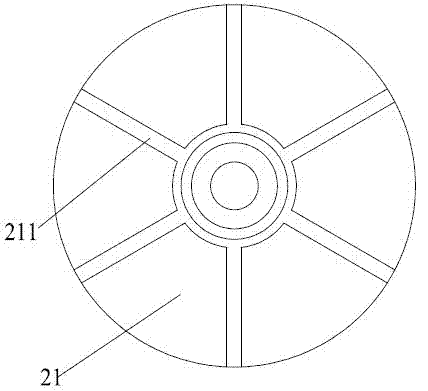
[0028] Several blades 211 are arranged a...

Embodiment 2

[0032] This embodiment is similar in structure to Embodiment 1, as Figure 6 and Figure 7 As shown, the difference is only that the movable grinding wheel 21 and the static grinding wheel 22 are matched up and down, the movable grinding wheel 21 and the static grinding wheel 22 are disc-shaped, the movable grinding wheel 21 is placed under the static grinding wheel 22, and the middle part of the static grinding wheel 22 is provided with a feeding port. 21 and static grinding 22 gap openings on the outside of the wheel are discharge openings. The rotation gap between the movable grinding wheel 21 and the static grinding wheel 22 gradually becomes smaller from the feed inlet to the discharge outlet.


PUM


Abstract

The invention relates to the technical field of soymilk makers, in particular to a grinding device. The grinding device comprises a motor, a moving grinding wheel and a fixed grinding wheel, wherein the moving grinding wheel and the fixed grinding wheel can rotate relatively, the moving grinding wheel is connected to the motor through a driving shaft, a running clearance is arranged between the moving grinding wheel and the fixed grinding wheel, the moving grinding wheel is in sliding connection with the driving shaft, and a plurality of blades are arranged at the bottom of the moving grinding wheel. Based on the design of the blades at the bottom of the moving grinding wheel, material is hardly blocked, and full grinding can be ensured.

Description

technical field [0001] The invention relates to the field of food grinding, in particular to a bean grinding device. Background technique [0002] With the development of food machinery, grinding soybean milk machine came into being. Compared with the blade type soybean milk machine, the grinding stone soybean milk machine has the advantages of high crushing degree and low noise. [0003] In the existing grinding type soybean milk machine, the material is added through the hopper, and then the movable grinding wheel and the static grinding wheel that can rotate relatively are used to achieve grinding, and then the slurry is discharged to the cup body from the gap between the inner and static grinding wheels. However, there are two problems in this structure. One is that the distance between the movable grinding wheel and the static grinding wheel is fixed. When encountering larger particles of material, it is easy to get stuck, and as the grinding progresses, the material b...

Claims


Application Information

Patent Timeline
Patent Type & Authority Applications(China)
IPC IPC(8): A47J43/046A47J43/07A47J31/00A47J31/44A23C11/10
Inventor 李前荣焦启华
Owner MIDEA GRP CO LTD
Why Eureka
Try Eureka