
Feedback magnetic chip suction device

A feedback and magnetic technology, applied in the field of mechanical processing, can solve the problems of inability to bend, no desquamation, no automatic desquamation function, etc., to avoid mutual interference and the effect of magnetic force is not affected

Inactive Publication Date: 2011-10-26
SHANGHAI DIANJI UNIV
View PDF8 Cites 3 Cited by
  • Summary
  • Abstract
  • Description
  • Claims
  • Application Information

AI Technical Summary

Problems solved by technology

[0002] In mechanical processing, a lot of metal chips (mostly iron chips) will be produced after the workpiece is cut. If these metal chips are not cleaned up in time, it will cause serious damage to the machine tool and parts. However, under normal circumstances, factories use manual The way of cleaning, the cleaning process is time-consuming and laborious, not only the cleaning effect is not good, but also the operator may be scratched
[0003] It is very difficult to clean up the metal shavings in the machine tools with complex structures and difficult to turn over, such as large box parts or machine tools with sealed structures, and in small spaces.
[0004] The Chinese patent No. 93230628.4 discloses a "powerful chip suction device", which is a screwdriver with a magnetic tip. The magnetic area is small, there is no automatic chip removal function, the suction is small, and the efficiency is low.
[0005] The Chinese patent No. 200720172852.4 discloses a "magnetic chip suction device", which is shaped like an electric iron and has a large magnetic area, but it is too bulky to carry and cannot clean the corners
[0006] The Chinese patent with the patent number 200820105989.2 discloses an "automatic chip suction device", which can only be fixed on the machine tool, has a limited scope of application, and has no chip removal function
[0007] The Chinese patent with the patent number 200920073099.2 discloses a "magnetic chip suction device", which has a rod structure, cannot be bent, has a large volume, and has a limited cleaning range, especially inside the box and complex parts.

Method used


Image

  • Feedback magnetic chip suction device
  • Feedback magnetic chip suction device
  • Feedback magnetic chip suction device

Examples


Embodiment Construction

[0024] A specific embodiment of a feedback type magnetic chip suction device of the present invention is given below with reference to the accompanying drawings.

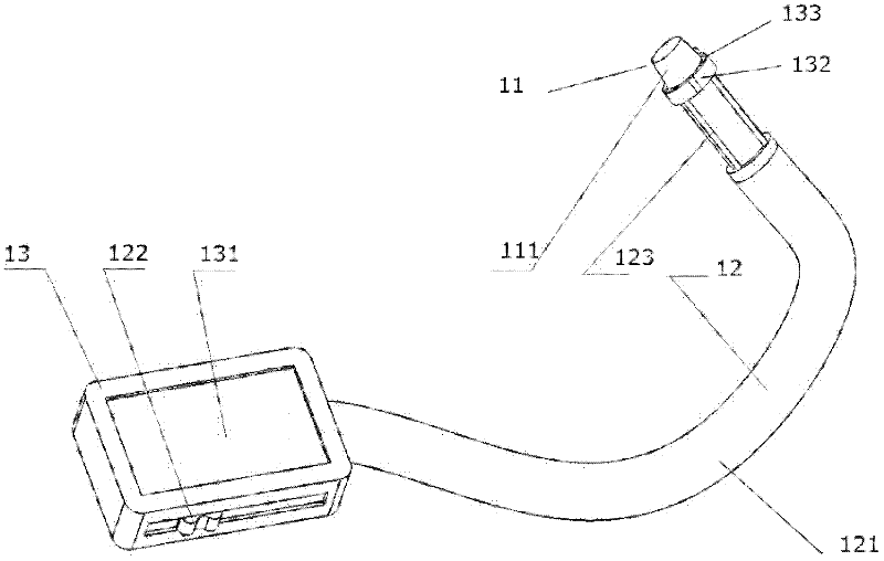
[0025] Please refer to figure 1 , which is a structural schematic diagram of the feedback magnetic chip suction device of the present invention. Such as figure 1 As shown, the present invention includes an adsorption body 11, which is connected to a linkage system 12 and a feedback system 13 in sequence.

[0026] The feedback system 13 includes: a screen 131, a power supply (not shown), an LED light 132 and a camera 133, the LED light 132 and the camera 133 are arranged on the adsorption body 11, the screen 131 and the linkage system 12 The first terminal is connected, the power supply is connected to the screen 131, and the power supply is used to supply power for the feedback system 13;

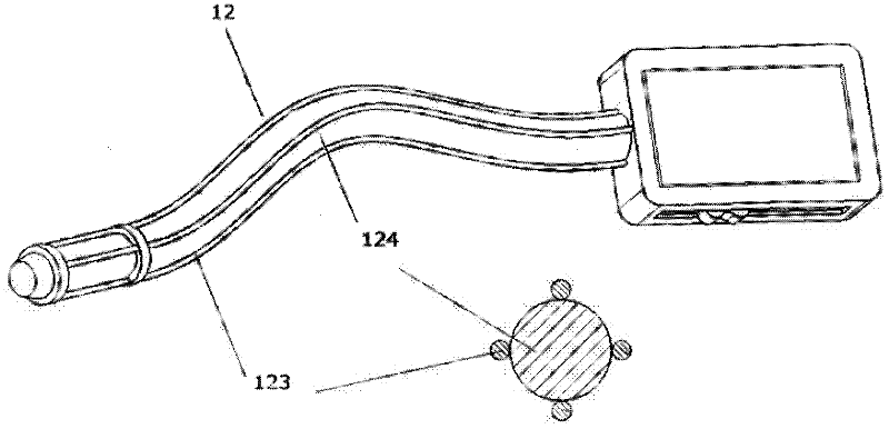
[0027] The outside of the linkage system 12 is a metal hose 121, and also includes a slider 122, the slider 122 is installed...


PUM


Abstract

The invention provides a feedback magnetic chip suction device, which comprises a sucking body, a link system and a feedback system, wherein the linking system and the feedback system are connected with the sucking body in sequence. The chip suction device can be flexed freely by using a coiler, is easy in operation and light in volume, can feed back the cleaning condition through a camera, has a good adsorption effect, can automatically remove chips without residues, and particularly solves the problems in dark and sealed working environments and small spaces, which cannot be solved by the conventional cleaning method.

Description

technical field [0001] The invention relates to a chip suction device in the field of mechanical processing, in particular to a feedback type magnetic chip suction device which is good at cleaning metal chips in a dark working environment, sealing the inside of a machine tool or a part, cleaning metal chips in a narrow space, and inspecting the internal structure of a circuit. Background technique [0002] In mechanical processing, a lot of metal chips (mostly iron chips) will be produced after the workpiece is cut. If these metal chips are not cleaned up in time, it will cause serious damage to the machine tool and parts. However, under normal circumstances, factories use manual The way of cleaning, the cleaning process is time-consuming and laborious, not only the cleaning effect is not good, but also the operator may be scratched. [0003] It is very difficult to clean up metal shavings in complex structures and difficult to turn equipment, such as large box parts or mach...

Claims


Application Information

Patent Timeline
IPC IPC(8): B08B7/00B03C1/02B23Q11/00
Inventor 陈斌于忠海赵俊凯尹燕华闫宁
Owner SHANGHAI DIANJI UNIV
Learn More