Clothes drying machine

A technology for drying machines and drying racks, which is applied in household dryers, other drying devices, washing devices, etc., can solve the problems of difficult body strength and body stability, overheating of support columns, and difficult design breakthroughs, etc. Improved strength and safety performance, easy switch operation, and the effect of visual observation

Active Publication Date: 2011-10-26
胡杰波
View PDF6 Cites 29 Cited by
  • Summary
  • Abstract
  • Description
  • Claims
  • Application Information

AI Technical Summary

Problems solved by technology

However, the new settings lead to an increase in the external volume of the casing, which is not conducive to collection, and also increases the cost of the product and the selling price
[0005] 3. In the existing clothes dryer, there are five parts from the bottom to the top: the legs, the machine casing, the air outlet shed, the support column, and the clothes hanging display rack. The structures are superimposed and connected from the bottom to the top. The overall strength is determined by the structure of each part itself and the structure of the connection of each part. The more connected parts, the more difficult it is to improve the strength and stability of the entire body
However, those skilled in the art can understand that there is limited room for improvement and optimization of the air outlet shed, so they are faced with the constraints of difficult design breakthroughs, high manufacturing difficulties, and increased material costs.
In addition, the increase in the weight and capacity of the clothes hung on the hanger is limited. If the clothes on the hanger are unevenly distributed or hung too much, it will cause overload deformation of the air shed components and the overall collapse of the dryer
[0006] 4. Since the support column in the prior art is located inside the cover body, the hot air inside the cover body will be directly conducted to the support column to overheat the support column, which will cause potential safety hazards in the use of the dryer

Method used


Image

  • Clothes drying machine
  • Clothes drying machine
  • Clothes drying machine

Examples


Embodiment 1

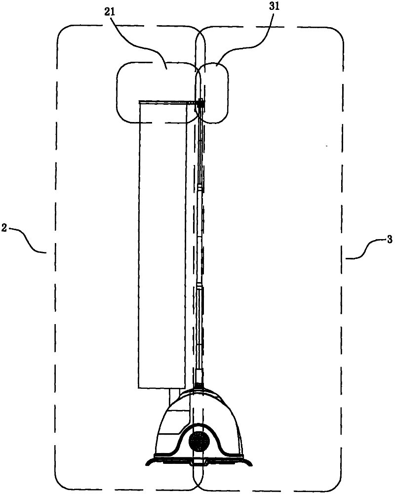
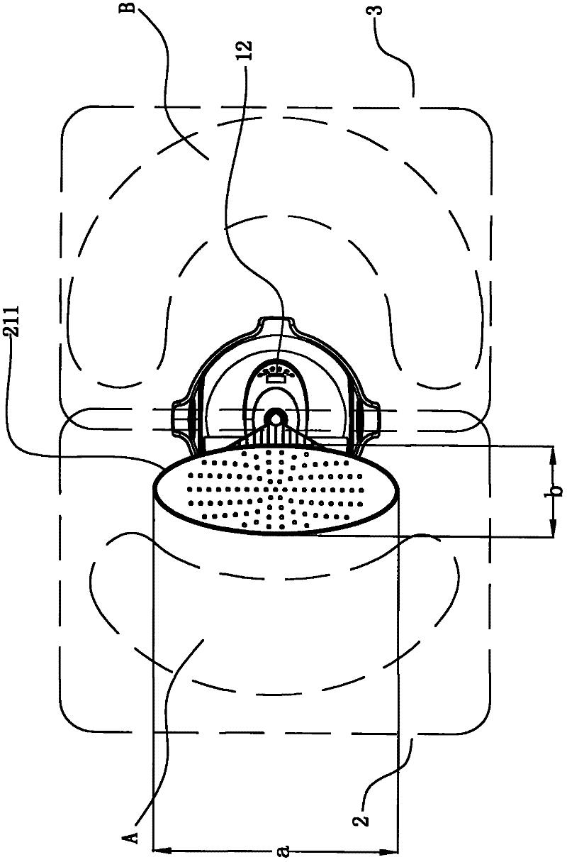
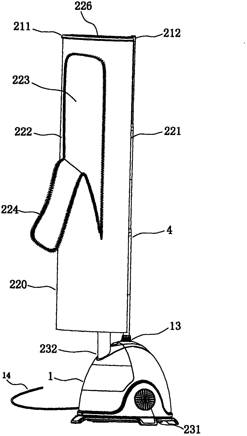
[0054] as attached figure 1 , figure 2 , image 3 , Figure 4 , Figure 5 Shown is an illustration of a preferred embodiment of the present invention. This high-efficiency dryer includes a support body 1 , a column 4 whose lower end is fixed on the support body 1 , and a cover 22 of a drying unit 2 located on one side of the column 4 , and a space unit 3 is formed on the other side of the column 4 . Wherein the drying unit 2 comprises a drying rack part 21 located on the left side of the column 4 and fixed on the upper end 41 of the column, a cover body 22 whose upper end hangs on the drying rack part 21 and naturally hangs down along the left side of the column 4, and is arranged inside the support body 1 The heating element 23. The shell of the support body 1 corresponding to the side of the space unit 3 is provided with a control panel 12 for controlling and operating the dryer, a power cord 14 for connecting the dryer to an external power source, an air inlet 231, an...

Embodiment 2

[0059] as attached Figure 6 , Figure 7 as well as Figure 8As shown, the difference from Embodiment 1 is that the heating component 23 in this embodiment is not inside the support body 1 , but is fixed on the upper end 41 of the column and on the side of the drying unit 2 . The upper end of the cover 22 is sleeved on the outer periphery of the supporting top frame 211, and the supporting top frame 211 is fixed in the groove 230 on the lower outside of the heating component 23. The cover 22 extends downward along the supporting top frame 211, and the bottom 220 of the cover is set There is a base plate 25 that expands the cover body bottom 20, and the base plate 25 is fixed on the lower end of the column 4 by side buckles 6, and the base plate 25 is provided with an outflow hole 251 for airflow to flow out. The inside of the housing of the heating component 23 is provided with a partition plate 234, the partition plate 234 divides the housing of the heating component 23 int...

Embodiment 3

[0061] The heating part 23 can also be fixed on any position of the column 4 between the drying frame part 21 and the support body 1, and also realizes the lower heating drying structure or the upper heating drying structure, and the inner space 223 of the cover body 22 Heating and blowing air can be implemented at any position. as attached Figure 9 and Figure 10 As shown, it is a lower heating drying structure. The heating component 23 is fixed on the lower end of the column body of the column 4 between the drying rack component 21 and the support body 1, and the partition plate 234 inside the housing of the heating component 23 separates the internal space of the heating component 23 into upper parts that communicate with each other. The slow air chamber 235 and the lower electrical appliance chamber 236, the electrical appliance chamber 236 has a groove toward the upper gentle air chamber 235, and a fan 238 and a heating element 237 are coaxially fixed on the partition ...


PUM


Abstract

The invention relates to a clothes drying machine which comprises a support body at the bottom, an erected upright post and a drying unit, wherein the erected upright post and the drying unit are positioned above the support body. The clothes drying machine is characterized in that the drying unit comprises a drying frame part, a cover body and a heating part, wherein the drying frame part is fixed at the upper end of the upright post and expanded on one side of the upright post; the cover body is fixed on the drying frame part and droops naturally along one side of the upright post to form an accommodating space; and the heating part is used for providing hot gas for the accommodating space in the cover body for drying clothes, a gas outlet and a gas inlet are arranged on the cover body, the heating part comprises a gas outlet interface, and the gas outlet interface of the heating part is hermetically communicated with the gas inlet of the cover body. The clothes drying machine is not only compact in structure and smooth in gravity center, but also can be conveniently observed and operated by a user; and furthermore, the clothes drying machine has higher machine body strength and safety performance, thus the stability of the whole machine carrying load is better, the clothes drying speed is fast, and the efficiency is high.

Description

technical field [0001] The invention relates to a clothes processing device, in particular to a household portable dryer. Background technique [0002] In today's home appliance market, many shed-type dryers for drying clothes have appeared, such as "a kind of clothes dryer" disclosed in Chinese patent CN2567261 and "a kind of shed-type clothes dryer" disclosed in Chinese patent CN2895492Y. Machine", although these two kinds of clothes dryers are convenient for home use, they also have the following deficiencies: [0003] 1. In the clothes dryer in the prior art, the lower end of the support column is supported in the middle of the air outlet shed, and the upper end of the support column is supported by a plurality of display racks for hanging clothes radially extended along the upper end, and a cylindrical flexible cover in the up and down direction The body surrounds the support column and the display frame, the top of which is forced to expand the display frame, the body...

Claims


Application Information

Patent Timeline
Patent Type & Authority Applications(China)
IPC IPC(8): D06F58/10D06F58/20D06F58/26D06F59/02
CPCD06F58/14
Inventor 胡杰波
Owner 胡杰波
Why Eureka
Try Eureka