Honeycomb-bundle tubular heat exchanger and manufacturing process thereof

A technology of heat exchanger and bundled tube, which is applied in the field of honeycomb bundled tube heat exchanger and its manufacturing process, which can solve the problems of complex manufacturing process, high cost, short fluid stroke in the shell, etc., and maximize the heat exchange area , The manufacturing process is simple, and the effect of solving the difficulty of sealing

Inactive Publication Date: 2011-10-26
佛山市德天电器有限公司
View PDF8 Cites 8 Cited by
  • Summary
  • Abstract
  • Description
  • Claims
  • Application Information

AI Technical Summary

Problems solved by technology

The shell-and-tube heat exchanger is composed of a tube bundle and a shell. Water flows in the shell, refrigerant flows in the tubes, and heat exchange is performed in a reverse convection manner. The disadvantage is that the fluid in the shell has a short stroke and the heat exchange efficiency is not high. The outlet water temperature is low, which cannot meet the demand, and the heat exchanger is bulky and expensive
Existing plate heat exchangers are assembled by pressing corrugated plates with special shapes, and non-metallic gaskets are embedded between the plates. A large number of plates and sealing heat are laminated to form many channels between the corrugated plates. Two different temperatures The medium flows in the separated channels for heat exchange. The plate heat exchanger has a large heat exchange area and good heat exchange effect, but its disadvantage is that the manufacturing process is complicated and the assembly requirements are high, which leads to the extremely expensive price of the product.

Method used


Image

  • Honeycomb-bundle tubular heat exchanger and manufacturing process thereof
  • Honeycomb-bundle tubular heat exchanger and manufacturing process thereof
  • Honeycomb-bundle tubular heat exchanger and manufacturing process thereof

Examples


Embodiment Construction

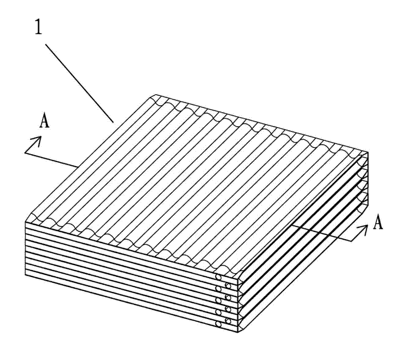
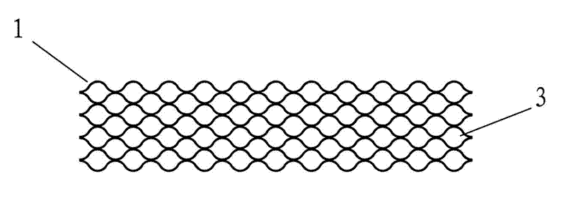
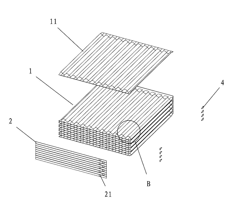
[0021] Reference Figure 1 to Figure 3 , An embodiment of the honeycomb bundle tube heat exchanger of the present invention includes a main body 1, which is formed by welding a plurality of corrugated heat exchange plates 11 pressed into a wave shape. The front and rear edges of the corrugated heat exchange plates 11 are The center line of the section is a straight line. The opposite sides of the adjacent corrugated heat exchange plates 11 are placed opposite each other. The wave crests and troughs that they touch are welded together, and the liquid flow channel 3 is formed between the distant wave crests and troughs. The liquid flow channel 3 between the heat exchange plates 11 constitutes a flow layer unit. The two sides of the flow layer unit are sealed by welding sealing plates. The end plate 2 covers the front and rear ports of the flow layer unit. The end plate 2 is at least A liquid flow hole 21 is opened, and the honeycomb bundle tube heat exchanger of the present inven...


PUM


Abstract

The invention discloses a honeycomb-bundle tubular heat exchanger which comprises a main body, wherein the main body is formed by the welding of a plurality of ripple heat exchanging plates which are compressed into the same shape; other parts except for two ends of a front end edge and a rear end edge are compressed into a straight edge along the central line of a cross section; the opposite two sides of adjacent ripple heat exchanging plates are placed opposite, and the contact wave crests and the wave troughs are welded together; a liquid channel is formed between the far wave crests and the wave troughs; the adjacent ripple heat exchanging plates and end plates and seal plates welded around form sealed flow layer units; two sides of each sealed flow layer unit are welded and sealed mutually through the sides of the ripple heat exchanging plates, and welded and sealed by utilizing the seal plates; the end plates seal and cover the front and rear end ports of each flow layer unit; and each end plate is at least provided with a liquid through hole. The designed heat exchanger has simple structure, low manufacturing cost and good heat exchange effect. The invention also discloses a manufacturing process of the honeycomb-bundle tubular heat exchanger.

Description

Technical field [0001] The invention relates to a heat exchange device, in particular to a honeycomb bundle tube heat exchanger and its manufacturing process. Background technique [0002] At present, many heat pump air-conditioning water heaters use water-cooled heat exchangers to prepare hot water, and at the same time replace the function of the condenser to improve work efficiency. The existing water-cooled heat exchangers mainly have two structures: tube and shell type and plate type. . The shell-and-tube heat exchanger is composed of a tube bundle and a shell. The water flows in the shell and the refrigerant flows in the tubes. The heat exchange is carried out in reverse convection. The disadvantage is that the stroke of the fluid in the shell is short and the heat exchange efficiency is not high. The outlet water temperature is low, which cannot meet the demand, and the heat exchanger is bulky and costly. The existing plate heat exchanger is assembled by pressing corruga...

Claims


Application Information

Patent Timeline
Patent Type & Authority Applications(China)
IPC IPC(8): F28D9/00F28F3/10F28F9/24B23P15/26
Inventor 林志辉
Owner 佛山市德天电器有限公司
Why Eureka
Try Eureka