
Electrically-charged oil-change device in transformer switch room and application method thereof

A switch room and transformer technology, applied in the direction of transformer/inductor cooling, transformer, variable transformer, etc., can solve the problems of incomplete oil treatment, failure to meet requirements, high cost, etc., to reduce the number of times and maintenance work time , Improve the safety and reliability of power supply, and reduce maintenance costs

Active Publication Date: 2011-10-26
JIANGSU ELECTRIC POWER CO
View PDF7 Cites 5 Cited by
  • Summary
  • Abstract
  • Description
  • Claims
  • Application Information

AI Technical Summary

Problems solved by technology

[0004] In the current power system, there are three main methods for live oil change of the on-load tap-changer of the main transformer: 1) directly use the oil filter to replace the waste oil. After pulling out, new oil can be added. During this period, there will be an oil-free state in the core. If an abnormal situation such as overvoltage occurs at this time, it will cause the contact to discharge and damage the equipment. There is a defect that the safety of the device cannot be guaranteed; 2 ) use the existing online oil filter device to filter oil. The equipment improvement of this scheme is simple to manufacture and has better safety performance, but the cost is high, and the treatment of oil products is usually not thorough. Compared with the oil change effect, there is a big gap, and there is can not meet the requirements

Method used


Image

  • Electrically-charged oil-change device in transformer switch room and application method thereof
  • Electrically-charged oil-change device in transformer switch room and application method thereof

Examples


Embodiment Construction

[0022] In order to make the content of the present invention more comprehensible, further description will be made below in conjunction with the accompanying drawings and specific embodiments.

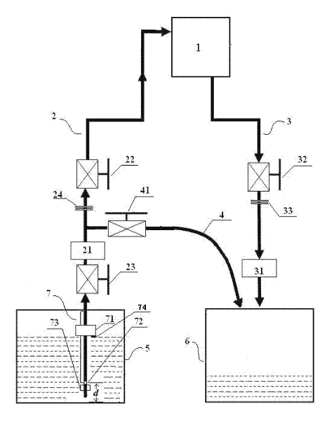
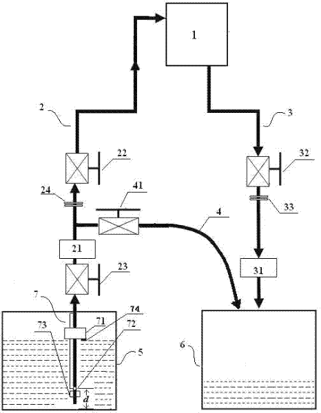
[0023] combine figure 1 It is a specific embodiment of the oil change vehicle of the present invention. The oil change vehicle includes a new oil storage chamber 5, an old oil storage chamber 6, an oil delivery pipeline 2, an oil extraction pipeline 3 and an exhaust pipeline 4, wherein the oil extraction pipeline The outlet of 3 is connected to the old oil storage chamber 6, and the inlet is used to connect to the oil tank 1 of the switch room. The pipeline between the outlet and the inlet is provided with a first oil filter 31 and a first valve 32 in sequence; the inlet of the oil pipeline 2 is connected to the new oil The storage chamber 5, the outlet is used to connect the oil tank 1 in the switch room, the pipelines between the inlet and the outlet are provided with a fourth valve ...


PUM


Abstract

The invention discloses an electrically-charged oil-change device in a transformer switch room and an application method thereof. The device comprises a fresh oil storage room, an old oil storage room, an oil transporting pipeline, an oil pumping pipeline and an exhaust pipeline, wherein the outlet of the oil pumping pipe is connected with the old oil storage room, a first oil filter and a first valve are arranged on the oil pumping pipeline in sequence; the inlet of the oil transporting pipe is connected with the fresh oil storage room, a second valve, a second oil filter and a fourth valve are arranged on the oil transporting pipeline in sequence; the inlet end of the exhaust pipe is connected with the oil transporting pipeline between the second valve and the second oil filter; and a third valve is arranged on the exhaust pipeline. When the device is in application, the outlet of the oil transporting pipe and the inlet of the oil pumping pipe are respectively connected with an oil tank in the switch room; through changing the combination of the switch condition of each valve, and combining with the oil filter driving and transformer oil pressure in the switch room, gas in the pipelines is subjected to an evacuation process and followed oil change. In the invention, the device can not only ensure the normal operation for a main transformer on-load tapping switch at the same time of realizing oil change, but also ensure the security and reduce the cost of the device.

Description

technical field [0001] The invention relates to the technical field of auxiliary equipment of a power system, in particular to a live oil change device for a transformer switch room and an application method thereof. Background technique [0002] Electricity is the basic industry of the national economy. The safety and stability of electric power production is related to the interests of thousands of households. The society has higher and higher requirements for safe power supply, especially for uninterrupted power supply and improving the reliability of power supply. The transformer on-load tap-changer is a device for changing the secondary output voltage of the transformer by performing gear switching operations under the load state of the transformer. The transformer oil in the on-load tap-changer room plays the role of extinguishing the arc and insulating. After each switch, the transformer oil will produce decomposition products and some free carbon, which will cause th...

Claims


Application Information

Patent Timeline
IPC IPC(8): H01F27/14H01F29/04G01F23/64
Inventor 丁彤李凯陈静民
Owner JIANGSU ELECTRIC POWER CO
Learn More