Controllable scouring system for cleaning heating surfaces of boiler and method

A heating surface and boiler technology, which is applied in the system field of cleaning the heating surface of the boiler, can solve the problems of mechanical parts wear energy, dead angle of soot cleaning, overfrequency of soot blowing, etc., and achieves small mechanical wear and impact, simple pipeline transformation, and high flow rate. require small effects

Inactive Publication Date: 2016-12-07
XI AN JIAOTONG UNIV
View PDF5 Cites 3 Cited by
  • Summary
  • Abstract
  • Description
  • Claims
  • Application Information

AI Technical Summary

Problems solved by technology

Due to the limited direction and area of ​​mechanical rapping, there is a dead angle for cleaning dust; steam soot blowing uses continuous high-pressure steam to blow the tube wall of the heating surface, which not only causes serious wear of mechanical parts but also consumes a lot of energy; The energy intensity of soot blowing is insufficient, and the ability to clean ash deposits is limited; gas pulse soot blowing uses combustible gas deflagration to generate shock waves to clean the heating surface, which can only be used in low temperature sections, and its application range is limited; water gun slag washing technology also needs to consider slag washing water recycling and discharge
At the same time, the soot blowing system of power plant boilers usually sets the soot blowing cycle first, and periodically cleans the soot according to the expected time. Insufficient ash or too frequent ash blowing affects the heat transfer efficiency of the heating surface of the boiler

Method used


Image

  • Controllable scouring system for cleaning heating surfaces of boiler and method
  • Controllable scouring system for cleaning heating surfaces of boiler and method

Examples


Embodiment Construction

[0018] The present invention will be further described below in conjunction with the accompanying drawings and specific embodiments. It should be understood that the components shown in the figures are schematic and not drawn according to specific dimensions, and the specific embodiments are used to illustrate the present invention and not limit the scope of the present invention.

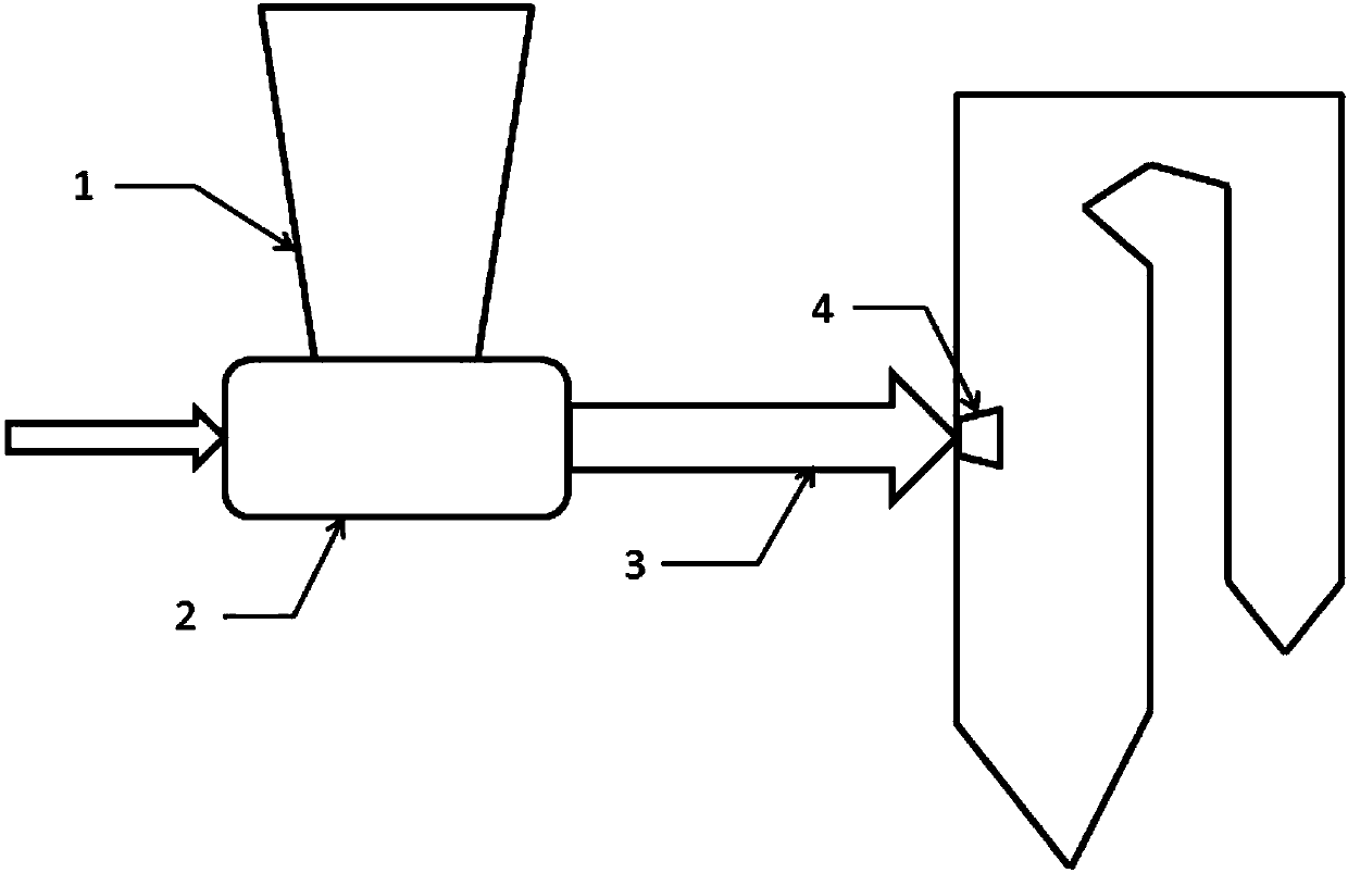
[0019] Such as figure 1 As shown, a controllable erosion system for cleaning the heating surface of the boiler according to the present invention includes several groups of sandblasting ports 4 installed on the boiler furnace wall, and several groups of sandblasting ports 4 connected to the boiler furnace wall. A soot blowing medium delivery pipe 3, and a particle supply system 1 and a gas-particle mixing device 2 connected to the soot blowing medium delivery pipe 3.

[0020] The particle supply system 1 supplies sand particles to the gas-particle mixing device 2, and the flowing gas enters the ga...


PUM


Abstract

The invention discloses a controllable scouring system for cleaning heating surfaces of a boiler and a method, particularly a method used for feeding a soot blowing medium (sand grains carried by flowing gas) into a hearth through sandblast openings in different positions to scour and clean the heating surfaces of the boiler. The method is characterized in that a plurality of sets of the sandblast openings are formed in the positions, behind a main combustion area and in front of the heating surfaces which have high probabilities of slag bonding and contamination, on the wall of the boiler, the sandblast openings are kept away from the high-temperature combustion area, the soot blowing medium with controllable flow rate and sand grain content is sprayed into the hearth, the sand grains are not fused and flow in the whole hearth to scour slag and soot on the heating surfaces of the boiler at a certain speed and angle. By virtue of the scouring and abrading functions of the sand grains on slag and soot on the heating surfaces of the boiler, slag and soot on the heating surfaces are abraded, crushed and separated, and the sand grains with favorable liquidity flow through all the heating surfaces along with flue gas, so that all the heating surfaces can be immediately and effectively scoured and cleaned without dead angles.

Description

technical field [0001] The invention relates to the technical field of cleaning the heating surface of a boiler, in particular to a system and method for cleaning the heating surface of a boiler by using flowing gas to send sand particles into a furnace to controllably erode the heating surface. Background technique [0002] my country's thermal power generation is dominated by coal. During the operation of coal-fired boilers, when the flue gas with a temperature higher than the ash melting point scours the heating surface, the molten ash in the flue gas will adhere to the heating surface to form slagging; when the flue gas When the gas temperature is lower than the ash melting point, the fly ash deposits on the heating surface of the boiler and easily forms ash deposits. Therefore, slagging and ash accumulation on the heating surface of boilers is a common problem in the operation of coal-fired boilers, especially when using coal with high alkali metal content (such as Zhund...

Claims


Application Information

Patent Timeline
Patent Type & Authority Applications(China)
IPC IPC(8): F23J1/00F23J3/00
CPCF23J1/00F23J3/00
Inventor 周屈兰罗沁澜李娜张义锋
Owner XI AN JIAOTONG UNIV
Why Eureka
Try Eureka