

Battery module, method for manufacturing same, and temperature adjustment system
A temperature regulation, battery module technology, applied in battery temperature control, batteries, secondary batteries, etc., can solve problems such as unit battery performance and life deviation, and achieve the effect of reducing temperature deviation
- Summary
- Abstract
- Description
- Claims
- Application Information
AI Technical Summary
Problems solved by technology
Method used
Image

Examples
Embodiment approach 1
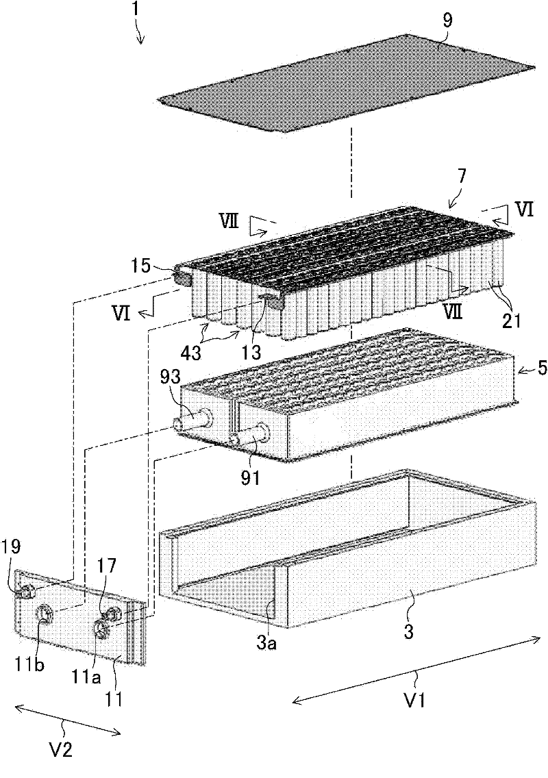
[0052] figure 1 It is an exploded perspective view of the battery module 1 in Embodiment 1 of the present invention.
[0053]In the battery module 1 of the present embodiment, the assembly 7 of the temperature adjustment unit 5 and the assembled battery is housed in the housing portion 3 a of the case 3 made of resin. The upper surface of the storage part 3a is covered with a cover 9 made of metal (for example, made of aluminum), and the front surface of the storage part 3a is covered with a front panel 11 made of resin.
[0054] The assembled battery assembly 7 is composed of seven assembled batteries 43 , 43 . . . connected in series, and each assembled battery 43 is composed of twenty unit cells 21 , 21 . In this specification, the direction in which unit cells 21, 21... are connected in parallel is referred to as "parallel direction V1", and the direction in which assembled batteries 43, 43... are connected in series is referred to as "serial direction V2". A positive co...
Embodiment approach 2
[0122] Embodiment 1 and Embodiment 2 differ in the structure of the temperature adjustment unit. Hereinafter, differences from Embodiment 1 described above will be mainly described.
[0123] Figure 17 (a) is a perspective view of the temperature adjustment unit 405 in this embodiment, Figure 17 (b) is its plan view. Figure 18 yes Figure 17 (b) A sectional view taken along the line XVIII-XVIII, Figure 19 is expressed in Figure 18 The shown cross-sectional view is a cross-sectional view of a state where each unit cell 21 is adhered and held on the holding portion 81 and liquid is supplied to the flow path 85 . In addition, in Figure 19 The side views of the unit cells 21, 21, . . . are described in .
[0124] The temperature adjustment unit 405 of this embodiment is formed by blow molding, and is composed of a resin molded body in which the first planar portion 473 , the second planar portion 475 , and the side wall portion 477 are integrally molded. The first fla...
Embodiment approach 3
[0141] The battery module in Embodiment 2 above includes one temperature adjustment unit formed by blow molding. However, in the blow molding method, generally, the molding of the resin molded product becomes difficult as the depth of the hollow portion of the resin molded product increases in the direction perpendicular to the air supply direction. Therefore, when the height of the unit cell 21 is increased, the unit cell 21 may protrude from the upper surface or the lower surface of the temperature adjustment unit 405 .
[0142] Therefore, in the temperature adjustment unit 505 in the third embodiment, the temperature adjustment units 405 and 405 in the above second embodiment are stacked in the height direction of the unit cell 21 . Figure 21 is a perspective view of the temperature adjustment unit 505 in this embodiment, Figure 22 yes Figure 21 The sectional view shown on line XXII-XXII, Figure 23 is expressed in Figure 22 The shown cross-sectional view is a cross...
PUM
| Property | Measurement | Unit |
|---|---|---|
| thickness | aaaaa | aaaaa |
Abstract
Description
Claims
Application Information