
Fusion control device and method for 3D printing

A technology of 3D printing and control devices, which is applied in manufacturing auxiliary devices, 3D object support structures, additive manufacturing, etc. It can solve the problems of inability to quickly adjust the nozzle, effectively segment the melt extrusion head, low dynamic control accuracy, and slow temperature control response speed and other problems, to achieve the effect of easy implementation, small demand for effective range, and fast response speed

Active Publication Date: 2017-12-01
金华市瑞意电气科技有限公司
View PDF3 Cites 4 Cited by
  • Summary
  • Abstract
  • Description
  • Claims
  • Application Information

AI Technical Summary

Problems solved by technology

Therefore, the slow temperature control response speed and low dynamic control precision of the traditional melting extrusion head have become one of the bottlenecks restricting the further improvement of FDM 3D printing speed and quality.
On the other hand, since the existing melting extrusion head generally adopts the control method of nozzle heating block heating and main body forced air cooling, it is impossible to realize the rapid adjustment of the local high temperature of the nozzle and the effective division of the overall high and low temperature areas of the melting extrusion head. At present, 3D printing The industry still lacks a melting control method that can quickly and accurately control the temperature of the nozzle to quickly switch between the molten state and the non-melting state, and effectively divide the overall high and low temperature regions

Method used


Image

  • Fusion control device and method for 3D printing
  • Fusion control device and method for 3D printing
  • Fusion control device and method for 3D printing

Examples


Embodiment Construction

[0022] Embodiments of the present invention will be described in detail below in conjunction with the accompanying drawings.

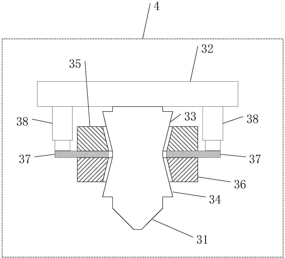
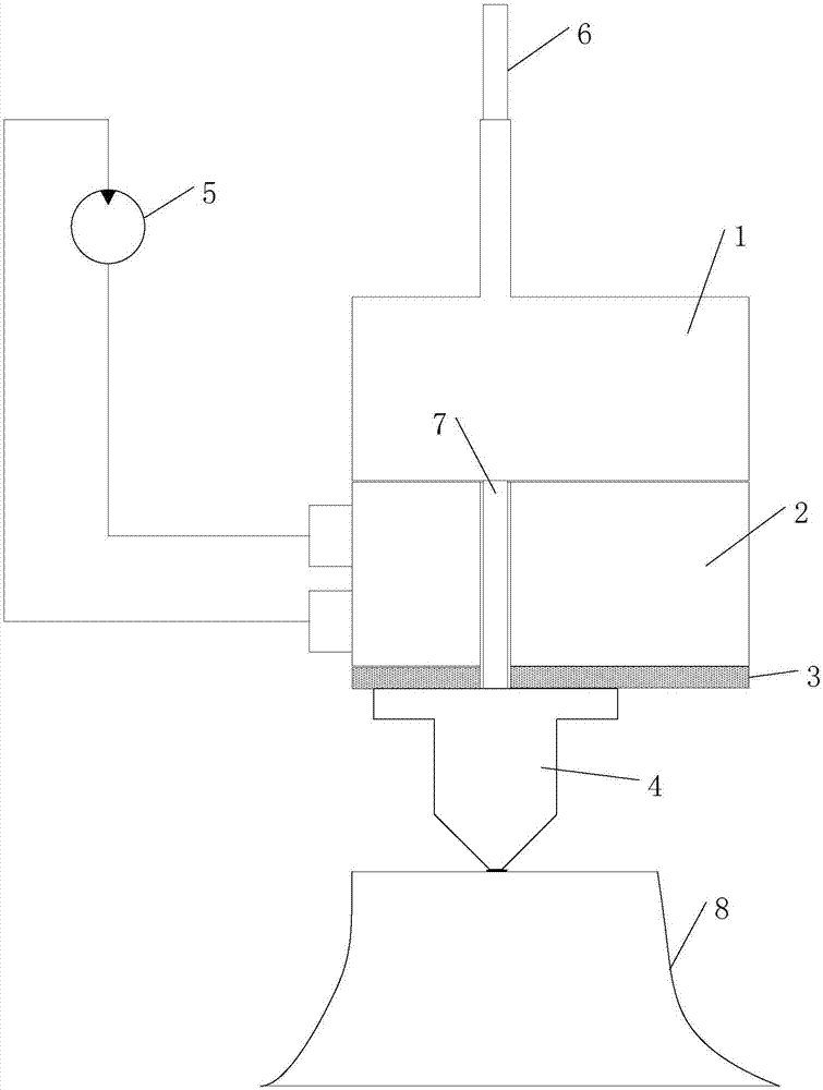
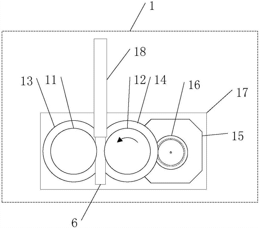
[0023] Such as figure 1 with 5As shown, a melting control device for 3D printing, the melting control device for 3D printing includes a main controller 60, a heating assembly, a heating controller 52 and a locking control assembly, wherein the heating controller 52, the locking The tight control components are all connected to the main controller 60 and operate under the control of the main controller 60. The heating components are connected to the heating controller 52. The heating components include a first constant temperature heating block 35, a second constant temperature heating block 36 and a heat resistance bracket 37 The heat-resistant bracket 37 is made of heat-insulating material. The first constant-temperature heating block 35 and the second constant-temperature heating block 36 are arranged on both sides of the heat-resistant bracket 37 a...


PUM


Abstract

The invention provides a fusion control device and method for 3D printing. The fusion control device comprises a main controller, a heating assembly, a heating controller and a locking control assembly. The heating controller and the locking control assembly both are connected with the main controller and operate under the control of the main controller. The heating assembly is connected with the heating controller. The heating assembly comprises a first constant-temperature heating block, a second constant-temperature heating block and a heat-resistant support. The heat-resistant support is made of a heat insulation material. The first constant-temperature heating block and the second constant-temperature heating block are correspondingly arranged on the two sides of the heat-resistant support and are matched with a nozzle on a 3D printer. The temperature working point of the first constant-temperature heating block is set as the fusion extrusion temperature, the temperature working point of the second constant-temperature heating block is set as a semi-solidification temperature for preventing fusion sagging, the first constant-temperature heating block and the second constant-temperature heating block are kept in the constant-temperature state under the control of the heating controller, and the locking control assembly controls the first constant-temperature heating block and the second constant temperature heating block to be in contact with or separated from the nozzle.

Description

technical field [0001] The invention belongs to the technical field of electromechanical control, in particular to a melting control device and method for 3D printing. Background technique [0002] Fused Deposition Modeling (FDM for short) is one of the current mainstream 3D printing technologies, which can print fine mechanical parts, and the printing cost is low and widely used. Among them, the melting extrusion head is the core component of the FDM3D printer. During the 3D printing process, when the servo mechanism drives the melting extrusion head to scan along the three-dimensional shape profile, the melting extrusion head feeds the wires made of ABS engineering plastics and other materials into the nozzle according to the scanning speed and layer thickness according to the set speed. deposited on the scanning surface. When processing some incoherent profiles and microstructure arrays, the FDM 3D printing process requires the melting extrusion head to switch between e...

Claims


Application Information

Patent Timeline
Patent Type & Authority Applications(China)
IPC IPC(8): B29C64/393B29C64/118B33Y10/00B33Y50/02
CPCB33Y10/00B33Y50/02
Inventor 林敏
Owner 金华市瑞意电气科技有限公司
Learn More