Fuel cell

A fuel cell and single cell technology, applied in fuel cells, fuel cell components, solid electrolyte fuel cells, etc., can solve problems such as battery performance degradation and electrode reaction area reduction, so as to suppress overflow and reduce temperature deviation. , the effect of stabilizing the output voltage

Inactive Publication Date: 2007-10-31
PANASONIC CORP
View PDF1 Cites 5 Cited by
  • Summary
  • Abstract
  • Description
  • Claims
  • Application Information

AI Technical Summary

Problems solved by technology

As a result, the reaction area of ​​the electrode decreases, and the performance of the battery decreases.

Method used


Image

  • Fuel cell
  • Fuel cell
  • Fuel cell

Examples


no. 1 approach

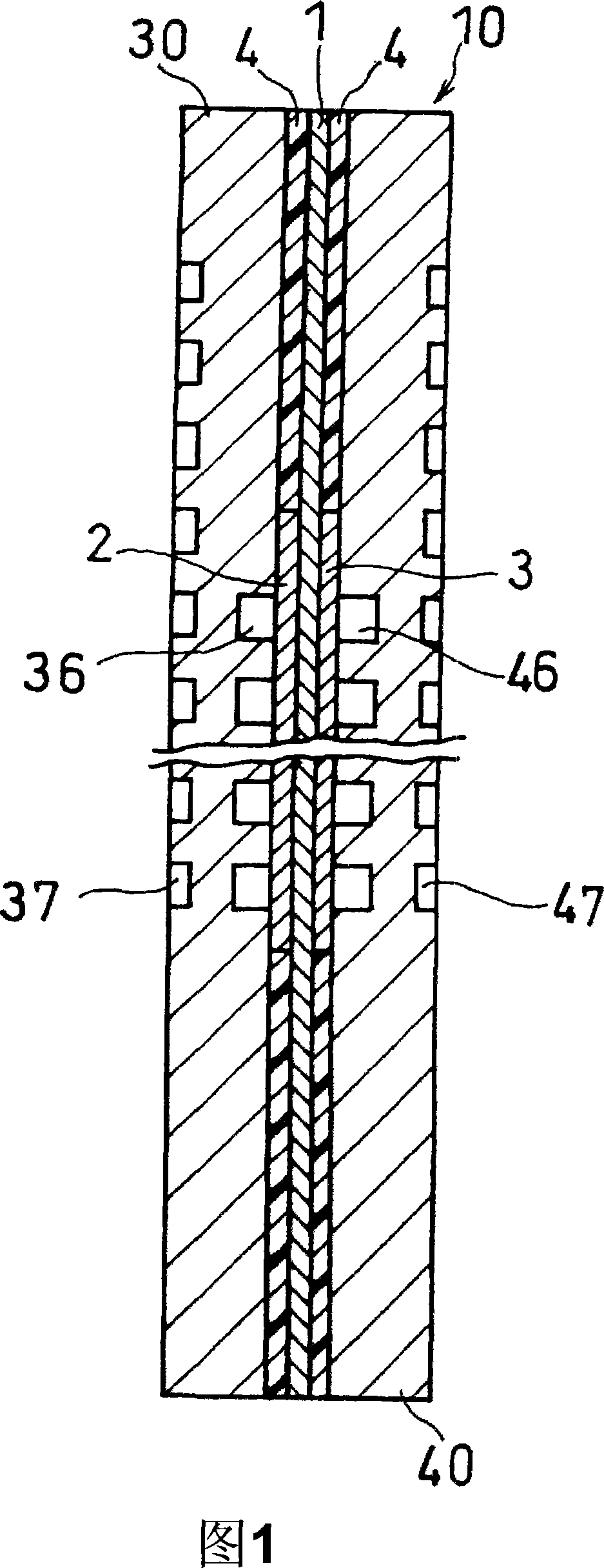
[0045] Fig. 1 is a schematic sectional view of a basic structure (single cell) of a fuel cell in a first embodiment of the present invention. The unit cell 10 includes: a polymer electrolyte membrane 1 having hydrogen ion conductivity as an example of a polymer electrolyte membrane; and a cathode 2 and an anode 3 sandwiching the polymer electrolyte membrane 1 . As the polymer electrolyte membrane 1 , a membrane made of perfluorosulfonic acid (Nafion (trade name) manufactured by E.I. du Pont de Nemours and Company) was used. The cathode and the anode consist of a catalyst layer connected to the polymer electrolyte membrane and a gas diffusion layer arranged outside it. As catalysts for the cathode and anode, carbon carrying an electrode catalyst (for example, platinum metal) is used.

[0046] The unit cell 10 has a polymer electrolyte membrane 1 , and a cathode-side separator 30 and an anode-side separator 40 sandwiching a membrane electrode assembly (MEA) composed of a cathod...

no. 2 approach

[0074] Next, a second embodiment of the fuel cell of the present invention will be described. The fuel cell (not shown) of this second embodiment has a different structure instead of the separators 30 and 40 of the single cell 10 of the first embodiment shown in FIG. The cells 10 of the embodiment are the same.

[0075] Hereinafter, the separator included in the fuel cell of the second embodiment (the second embodiment of the separator of the present invention) will be described.

[0076] The fuel cell of this embodiment is the same as that described above except that the shape of the cooling water flow path in the cathode side separator is the structure shown in FIG. 8 and the shape of the cooling water flow path in the anode side separator is the structure shown in FIG. 9 . Embodiment 1 is the same.

[0077] The cooling water flow path 57 of the cathode-side separator 30A consists of a portion (second cooling portion) 57a connected to the inlet side of the inlet-side manif...

Embodiment 1

[0090] The gas diffusion layer uses carbon woven fabric (GF-20-E) manufactured by Nippontan Co., Ltd. with a diameter of 20 to 70 μm in more than 80% of the pores as the base material, and polytetrafluoroethylene (PTFE) is dispersed in the A dispersion liquid is obtained in pure water of the surfactant, and the base material is immersed in the dispersion liquid. Thereafter, the base material was passed through a far-infrared drying furnace, and fired at 300° C. for 60 minutes. The amount of waterproof resin (PTFE) in the substrate at this time is 1.0 mg / cm 2 .

[0091]Then the paint for coating was produced. Carbon black was added to a solution obtained by mixing pure water and a surfactant, and dispersion treatment was performed for 3 hours with a planetary mixer. PTFE and water were added to the obtained dispersion, followed by kneading for another 3 hours. Among them, as the surfactant, a commercially available product named Triton X-100 was used.

[0092] The paint fo...


PUM

PropertyMeasurementUnit
diameteraaaaaaaaaa

Abstract

The temperature of cooling fluid in an entrance side manifold is raised, in power generation, by influence of the temperature of a heat generation section of a cell. This causes variation in the temperature of each single cell in a fuel cell stack, causing flooding and variation in an output voltage. The invention provides a fuel cell in which a rise in temperature of cooling fluid in an entrance side manifold is suppressed, that has high durability, and that provides a stable output voltage. The fuel cell has cooling fluid flow paths in a cathode side separator plate and an anode side separator plate, the flow paths connecting an entrance side manifold and exit side manifold for the cooling fluid. The cooling fluid flow paths are composed of first cooling sections for cooling heat generation sections that are regions corresponding to a cathode and an anode and of second cooling sections each positioned between a first cooling section and an entrance side manifold for the cooling fluid.

Description

technical field [0001] The present invention relates to a fuel cell used in a household cogeneration system, a motorcycle, an electric vehicle, a hybrid electric vehicle, etc., particularly a polymer electrolyte fuel cell. More specifically, the present invention relates to obtaining a fuel cell that is less prone to flooding and has excellent durability by reducing temperature fluctuations in individual cells in a fuel cell stack. Background technique [0002] A fuel cell using a polymer electrolyte having cation (hydrogen ion) conductivity is a battery that simultaneously generates electricity and heat by electrochemically reacting a fuel gas containing hydrogen and an oxidant gas containing oxygen such as air. This fuel cell is basically composed of a polymer electrolyte membrane having hydrogen ion conductivity for selectively transporting hydrogen ions, and a pair of electrodes arranged on both surfaces of the polymer electrolyte membrane. This pair of electrodes inclu...

Claims


Application Information

Patent Timeline
Patent Type & Authority Applications(China)
IPC IPC(8): H01M8/02H01M8/10
CPCH01M8/0267H01M8/04089H01M8/0258H01M8/0263H01M8/0247Y02E60/50H01M8/04029H01M8/1002H01M8/241H01M8/1007H01M8/2457H01M8/2483
Inventor 鹈木重幸竹口伸介武部安男
Owner PANASONIC CORP
Why Eureka
Try Eureka