Bladeless fan

A bladeless fan and base technology, applied in non-variable pumps, pump devices, machines/engines, etc., can solve problems such as uneven wind, high blade speed, difficult cleaning of blades and outer covers, and achieve remarkable results. The effect of large air volume

A bladeless fan and base technology, applied in non-variable pumps, pump devices, machines/engines, etc., can solve problems such as uneven wind, high blade speed, difficult cleaning of blades and outer covers, and achieve remarkable results. The effect of large air volume

CN102230482AInactive Publication Date: 2011-11-02王瑛

Image

  • Bladeless fan
  • Bladeless fan
  • Bladeless fan

Examples


Embodiment Construction

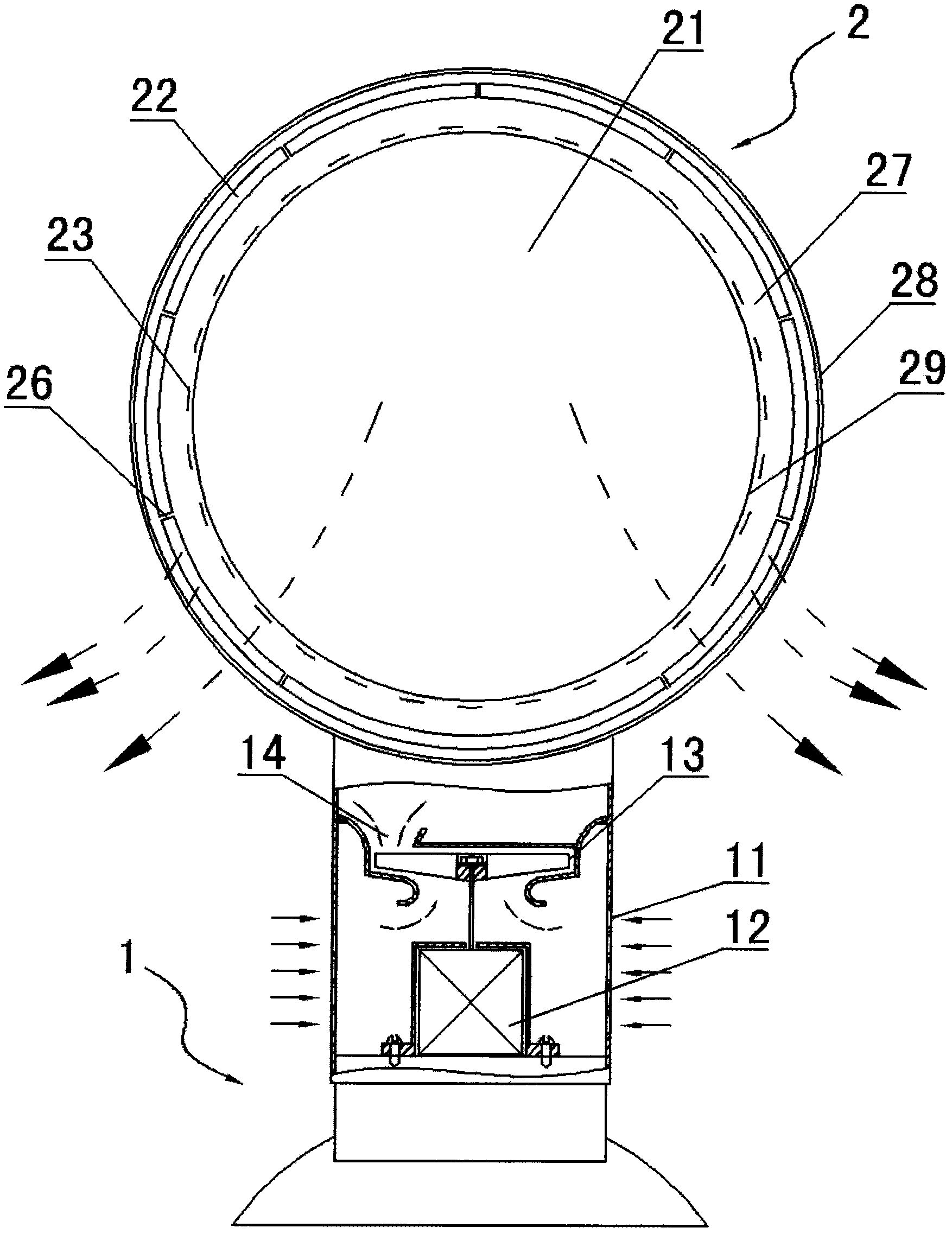
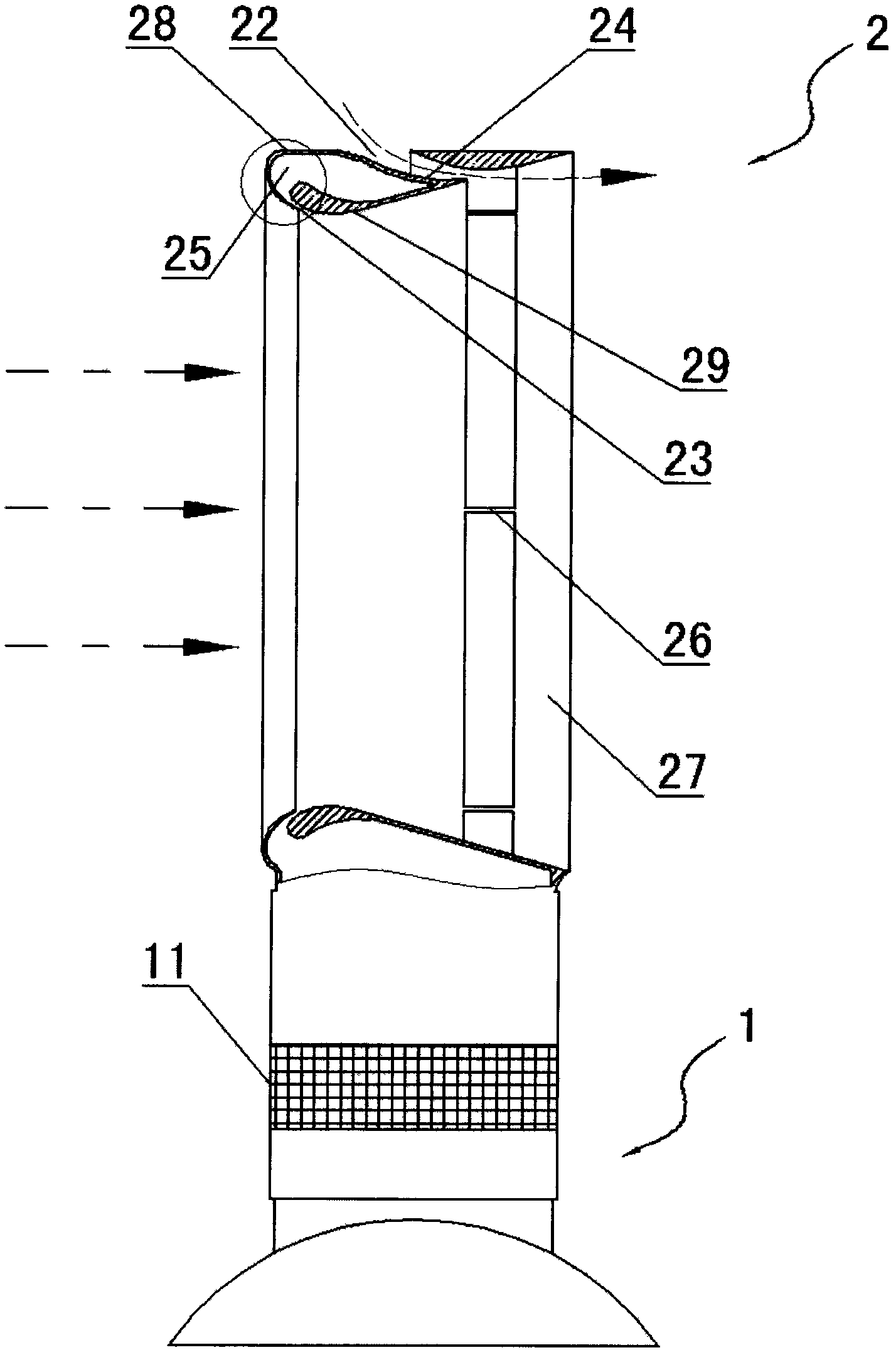
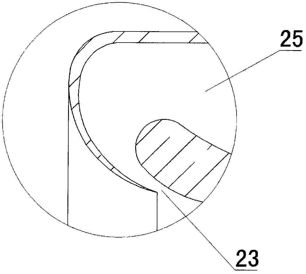
[0022] Such as figure 1 , figure 2 , image 3 with Figure 4 As shown, the bladeless fan is composed of a base 1 and an airflow injection device 2 positioned above the base 1. An air inlet 11 is provided on the shell of the base 1. A motor 12 is arranged inside the base 1. The motor 12 Drive the rotating impeller 13, the air channel 14, the air flow injection device 2 is a hollow ring structure, the hollow part is the first air flow channel 21, and the air flow injection device 2 is provided with an annular second air flow channel 22 and an annular The exhaust port 23. The impeller 13 is arranged in the casing of the base 1 to help inhale and pressurize the air, and then blow the air into the air jet device 2 . The air jet device 2 is a hollow annular structure, and may also be square or elliptical, such as Figure 5 As shown, as long as the axis is symmetrical.

[0023] The air inlet of the second air flow channel 22 is located on the outer wall of the air jetting devi...


PUM


Abstract

The invention discloses a bladeless fan. The bladeless fan consists of a base and an air flow jetting device which is positioned above the base, wherein an air inlet is formed on the shell of the base; the air flow jetting device has a hollow ring-shaped structure; a hollow part is a first air flow channel; and a ring-shaped second air flow channel and a ring-shaped air outlet are formed on the air flow jetting device. The bladeless fan is provided with the first air flow channel which is the same as that of the common bladeless fan, and is also provided with the second air flow channel, and air on the back side and the lateral sides of the fan can be extracted effectively, so that the fan has larger air volume and a more obvious effect.

Description

technical field [0001] The invention relates to a fan, which belongs to the optimization technology of the fan. Background technique [0002] The existing fan drives the blades to rotate through the motor, and the air is pressurized and accelerated by the blades and then blows to the user. Be careful that it will cause injury, although most fans use outer covers to surround the blades to reduce danger; second, the blades and outer covers are difficult to clean; third, the blades will produce noise during rotation, which will disturb users; The 4th, because air-flow changes when passing through blade surface, the wind that blows out is not uniform, and the user can feel the strong wind of bursts like pulse. [0003] In the patent documents with the application number 200810177843.3 and the application number 200810177844.8, a fan is disclosed, which consists of a base and an annular exhaust port installed on the base. The inner channel of the airflow and the exhaust port, t...

Claims


Application Information

Patent Timeline
02 Nov 2011
Publication
CN102230482A
IPC
F04F5/16; F04F5/46
CPC
F04D25/08; F04F5/16; F04F5/46
Inventors
李耀强