
Flat solar air heat exchanger

An air heat exchanger and flat-panel solar technology, applied in the field of solar collectors, can solve the problems of uneven distribution of heat transfer medium, low heat conduction efficiency of heat-absorbing plate core, and large heat loss, so as to achieve uniform distribution of heat transfer medium and reduce heat energy The effect of small loss and heat loss

Inactive Publication Date: 2011-11-02
GUANGDONG FIVESTAR SOLAR ENERGY
View PDF4 Cites 8 Cited by
  • Summary
  • Abstract
  • Description
  • Claims
  • Application Information

AI Technical Summary

Problems solved by technology

[0002] The flat panel solar collector is mainly composed of a heat-absorbing plate core, a solar selective absorption coating coated on the upper surface of the heat-absorbing plate core, a pipe welded with the heat-absorbing plate core, a transparent cover plate, a thermal insulation layer and The outer casing is composed of a header pipe welded at both ends of the row pipe. The heat transfer medium is distributed from the header pipe at one end of the row pipe, and then flows into each row pipe to exchange heat with the heat-absorbing plate core, and then flows from the other end of the row pipe. One header flows out, because the heat transfer medium can only be distributed once, resulting in uneven distribution of the heat transfer medium, and cannot fully exchange heat with the heat-absorbing plate core, resulting in a large loss of heat energy, large heat loss, and the heat conduction of the heat-absorbing plate core low efficiency

Method used


Image

  • Flat solar air heat exchanger
  • Flat solar air heat exchanger
  • Flat solar air heat exchanger

Examples


Embodiment Construction

[0010] The following are the best examples of the flat solar air heat exchanger of the present invention, which do not limit the protection scope of the present invention.

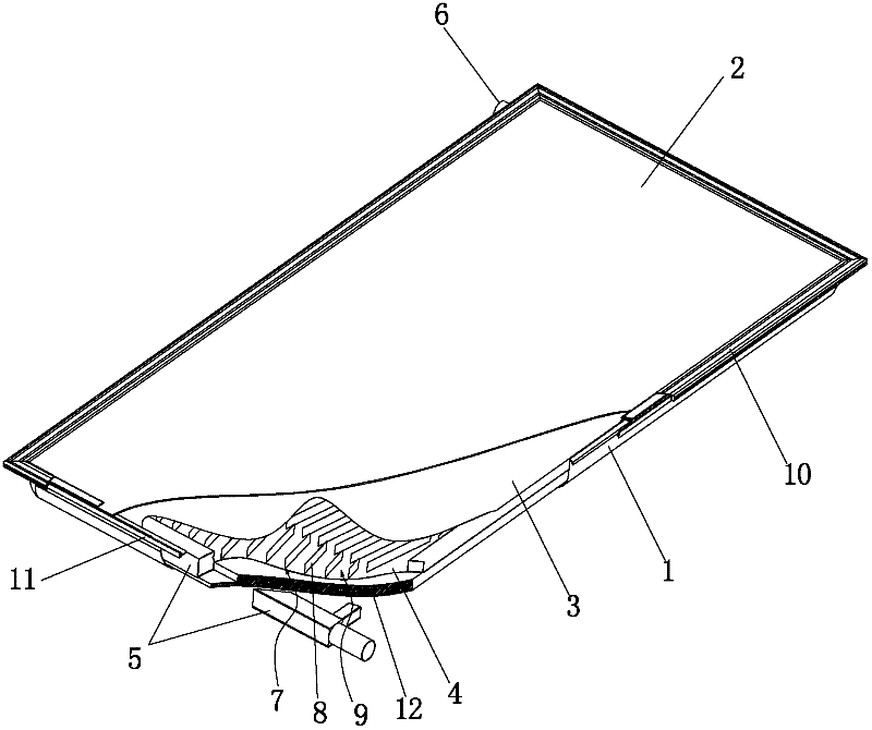
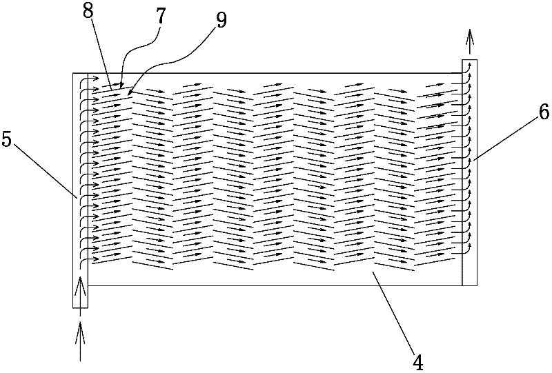
[0011] refer to figure 1 , figure 2 , providing a flat solar air heat exchanger, including a shell 1, a transparent cover 2 installed on the upper part of the shell 1, and a solar heat absorbing plate sequentially arranged in a closed space between the transparent cover 2 and the shell 1 3. The heat exchange plate 4, the cold air intake pipe 5 located at one end of the heat exchange plate 4 and the hot air outlet pipe 6 located at the other end of the heat exchange plate 4 are arranged in the closed space between the transparent cover plate 2 and the casing 1, The air inlet of the cold air inlet pipe 5 and the outlet of the hot air outlet pipe 6 extend out of the shell 1, the cold air inlet pipe 5 and the hot air outlet pipe 6 are provided with air holes, and the heat exchange plate 4 is provided with se...


PUM


Abstract

The invention discloses a flat solar air heat exchanger. The flat solar air heat exchanger comprises a shell, a transparent cover plate arranged on the upper part of the shell, a solar heat absorption plate and a heat exchange plate which are arranged in a closed space sequentially between the transparent cover plate and the shell, a cold air inlet tube which is arranged in the closed space between the transparent cover plate and the shell and positioned at one end of the heat exchange plate, and a hot air outlet tube which is arranged in the closed space between the transparent cover plate and the shell and positioned at the other end of the heat exchange plate, wherein a plurality of heat exchange units are arranged on the heat exchange plate; each heat exchange unit consists of a plurality of heat exchange fins which are arranged on the heat exchange plate at intervals; an air flow channel is formed between two adjacent heat exchange fins; in a direction of air flow, one air flow channel of the former heat exchange unit of the two adjacent heat exchange units is communicated with two air flow channels of later heat exchange unit of the two adjacent heat exchange units, so heat transmission media can be subjected to pressure and flow distribution for many times; furthermore, the heat transmission media are distributed uniformly, so full heat exchange between the heat transmission media and the solar heat absorption plate can be realized and the heat transmission efficiency is high.

Description

technical field [0001] The invention relates to a solar heat collector, more specifically, to a flat-plate solar air heat exchanger. Background technique [0002] The flat panel solar collector is mainly composed of a heat-absorbing plate core, a solar selective absorption coating coated on the upper surface of the heat-absorbing plate core, a pipe welded to the heat-absorbing plate core, a transparent cover plate, a thermal insulation layer and The outer casing is composed of a header pipe welded at both ends of the row pipe. The heat transfer medium is distributed from the header pipe at one end of the row pipe, and then flows into each row pipe to exchange heat with the heat-absorbing plate core, and then flows from the other end of the row pipe. One header flows out, because the heat transfer medium can only be distributed once, resulting in uneven distribution of the heat transfer medium, and cannot fully exchange heat with the heat-absorbing plate core, resulting in a ...

Claims


Application Information

Patent Timeline
IPC IPC(8): F24J2/05F24J2/22F24J2/50F24S10/40F24S10/55
CPCF24J2/202Y02E10/44F24J2/4647F24S10/502F24S80/30
Inventor 杨宪杰
Owner GUANGDONG FIVESTAR SOLAR ENERGY
Learn More