Laser radar coaxial transmitting and receiving system and coaxial adjustment method thereof
A technology of laser radar and receiving system, which is applied in the direction of radio wave measurement system, optical device, measuring device, etc., can solve the problem of long coaxial adjustment period of laser radar receiving and receiving optical path, etc., and achieve simple and intuitive adjustment process, simple structure, and easy The effect of installation and debugging
- Summary
- Abstract
- Description
- Claims
- Application Information
AI Technical Summary
Problems solved by technology
Method used
Image
Examples
specific Embodiment approach 1
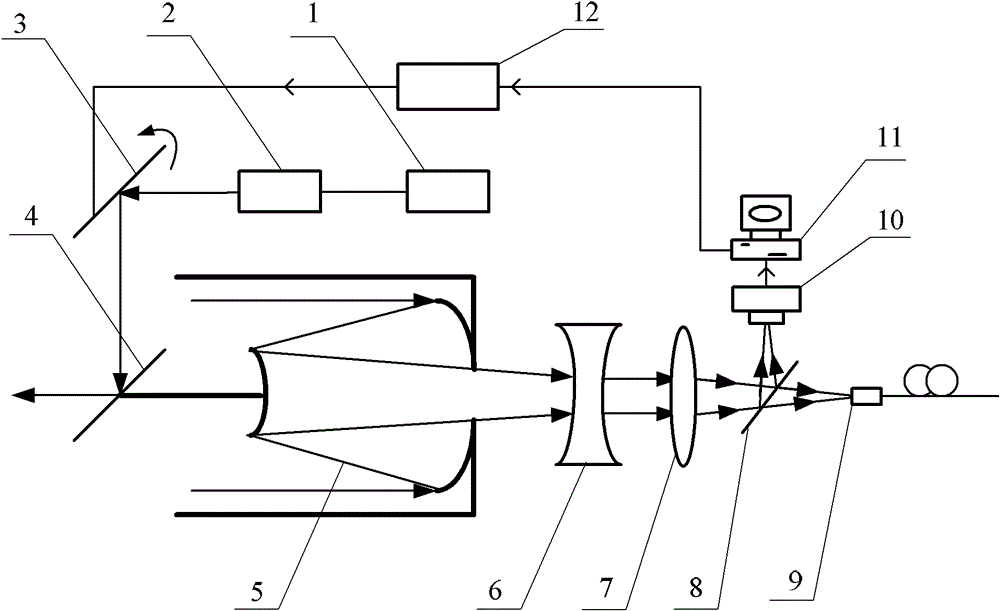
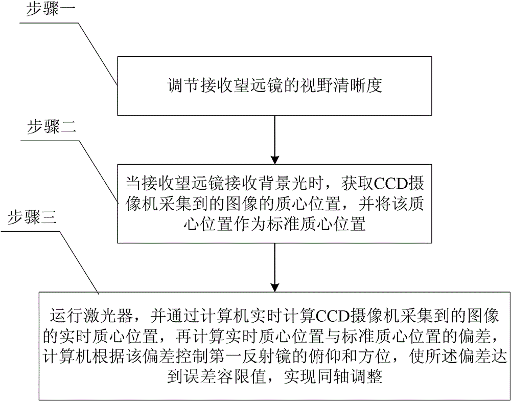
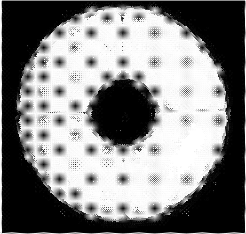
[0019] Specific implementation mode one: the following combination figure 1 with image 3 Describe this embodiment mode, this embodiment mode is a kind of laser radar coaxial transmitting and receiving system, it is made up of laser device 1, transmitting telescope 2, first mirror 3, second reflecting mirror 4, receiving telescope 5, concave lens 6, convex lens 7. Composed of beam splitter 8, optical fiber 9, CCD camera 10, computer 11 and motor rotation control system 12,
[0020] The laser beam generated by the laser 1 is expanded and collimated by the transmitting telescope 2, and then enters the atmosphere after being reflected by the first reflector 3 and the second reflector 4, and the echo signal of the laser beam entering the atmosphere is received by the receiving telescope 5. The outgoing light beam of the telescope 5 is converted into parallel light by the concave lens 6 and enters the convex lens 7. The converging light beam collected by the convex lens 7 is trans...
specific Embodiment approach 2
[0025] Specific implementation mode two: the following combination figure 1 Describe this embodiment, this embodiment is a further description of Embodiment 1, the reflection surface of the second reflector 4 forms an included angle of 45 degrees with the central axis of the receiving telescope 5, and the central axis of the receiving telescope 5 passes through the first The center of the second mirror 4. Others are the same as the first embodiment.
[0026] The second reflector 4 is a fixed reflector, which does not rotate during the entire coaxial adjustment process. combine figure 1 In the way of placing the first reflector 3, the reflective surface of the second reflector 4 and the central axis of the receiving telescope 5 are placed at an angle of 45 degrees, which can effectively reduce the time required for optical coaxial adjustment.
specific Embodiment approach 3
[0027] Specific implementation mode three: the following combination figure 1 Illustrate this embodiment, this embodiment is a further description of Embodiment 1 or 2, the receiving telescope 5 is a Cassegrain type, the 5 secondary mirrors of the receiving telescope and the second reflector 4 are circular, and the second reflector The diameter of mirror 4 is less than the diameter of receiving telescope 5 secondary mirrors. Others are the same as the first or second embodiment.
[0028] The light transmission size of the second reflector 4 should be slightly larger than the spot size of the laser beam generated by the laser 1 .
PUM
 Abstract
Description
Claims
Application Information
 - R&D
- Intellectual Property
- Life Sciences
- Materials
- Tech Scout
- Unparalleled Data Quality
- Higher Quality Content
- 60% Fewer Hallucinations
Browse by: Latest US Patents, China's latest patents, Technical Efficacy Thesaurus, Application Domain, Technology Topic, Popular Technical Reports.
© 2025 PatSnap. All rights reserved.Legal|Privacy policy|Modern Slavery Act Transparency Statement|Sitemap|About US| Contact US: help@patsnap.com


