Laser radar coaxial transmitting and receiving system and coaxial adjustment method thereof

A technology of laser radar and receiving system, which is applied in the direction of radio wave measurement system, optical device, measuring device, etc., can solve the problem of long coaxial adjustment period of laser radar receiving and receiving optical path, etc., and achieve simple and intuitive adjustment process, simple structure, and easy The effect of installation and debugging

Inactive Publication Date: 2011-11-02
HARBIN INST OF TECH
View PDF4 Cites 45 Cited by
  • Summary
  • Abstract
  • Description
  • Claims
  • Application Information

AI Technical Summary

Problems solved by technology

[0004] The purpose of the present invention is to solve the problem that the coaxial adjustment cycle of the laser radar receiving and receiving optical path is relatively long, and provide a coaxial transmitting and receiving system of the laser radar and a coaxial adjusting method of the system

Method used


Image

  • Laser radar coaxial transmitting and receiving system and coaxial adjustment method thereof
  • Laser radar coaxial transmitting and receiving system and coaxial adjustment method thereof
  • Laser radar coaxial transmitting and receiving system and coaxial adjustment method thereof

Examples


specific Embodiment approach 1

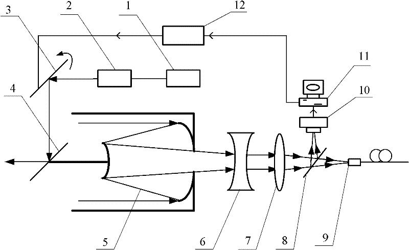
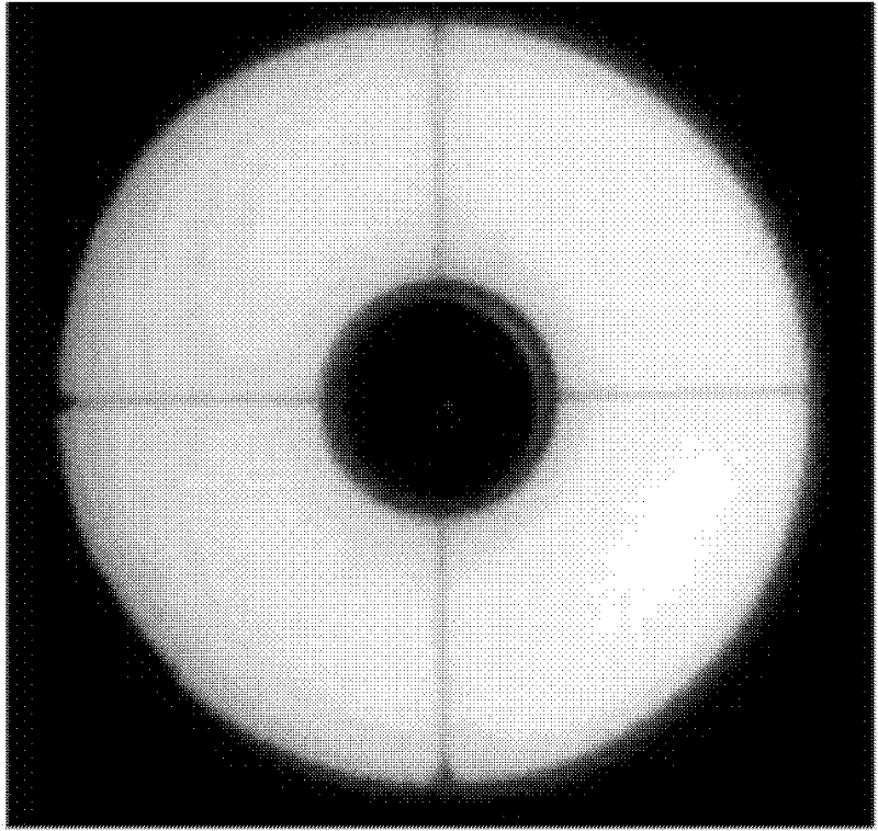
[0019] Specific implementation mode one: the following combination figure 1 with image 3 Describe this embodiment mode, this embodiment mode is a kind of laser radar coaxial transmitting and receiving system, it is made up of laser device 1, transmitting telescope 2, first mirror 3, second reflecting mirror 4, receiving telescope 5, concave lens 6, convex lens 7. Composed of beam splitter 8, optical fiber 9, CCD camera 10, computer 11 and motor rotation control system 12,

[0020] The laser beam generated by the laser 1 is expanded and collimated by the transmitting telescope 2, and then enters the atmosphere after being reflected by the first reflector 3 and the second reflector 4, and the echo signal of the laser beam entering the atmosphere is received by the receiving telescope 5. The outgoing light beam of the telescope 5 is converted into parallel light by the concave lens 6 and enters the convex lens 7. The converging light beam collected by the convex lens 7 is trans...

specific Embodiment approach 2

[0025] Specific implementation mode two: the following combination figure 1 Describe this embodiment, this embodiment is a further description of Embodiment 1, the reflection surface of the second reflector 4 forms an included angle of 45 degrees with the central axis of the receiving telescope 5, and the central axis of the receiving telescope 5 passes through the first The center of the second mirror 4. Others are the same as the first embodiment.

[0026] The second reflector 4 is a fixed reflector, which does not rotate during the entire coaxial adjustment process. combine figure 1 In the way of placing the first reflector 3, the reflective surface of the second reflector 4 and the central axis of the receiving telescope 5 are placed at an angle of 45 degrees, which can effectively reduce the time required for optical coaxial adjustment.

specific Embodiment approach 3

[0027] Specific implementation mode three: the following combination figure 1 Illustrate this embodiment, this embodiment is a further description of Embodiment 1 or 2, the receiving telescope 5 is a Cassegrain type, the 5 secondary mirrors of the receiving telescope and the second reflector 4 are circular, and the second reflector The diameter of mirror 4 is less than the diameter of receiving telescope 5 secondary mirrors. Others are the same as the first or second embodiment.

[0028] The light transmission size of the second reflector 4 should be slightly larger than the spot size of the laser beam generated by the laser 1 .


PUM


Abstract

The invention relates to a laser radar coaxial transmitting and receiving system and a coaxial adjustment method thereof and belongs to the technical field of laser radar, and the method can be used for solving the problem that the coaxial adjustment period of a laser radar receiving and transmission light path is long. The laser radar coaxial transmission and receiving system is composed of a laser device, a transmission telescope, a first reflecting mirror, a second reflecting mirror, a receiving telescope, a concave lens, a convex lens, a beam splitter, an optical fiber, a CCD (Charge Coupled Device) camera, a computer and a motor rotation control system. The coaxial adjustment method based on the system comprises the following steps: adjusting the visual field definition of the receiving telescope; when the receiving telescope receives background light, obtaining a standard centroid position acquired by the CCD camera; starting the laser device, calculating the real-time centroid position of an image acquired by the CCD camera in real time, and calculating the deviation between the two centroid positions; and controlling the pitching and bearing of the first reflecting mirror until the deviation reaches an error tolerance, thus realizing the coaxial adjustment. The method provided by the invention is applicable to the coaxial adjustment of a laser radar receiving and transmission system.

Description

technical field [0001] The invention relates to a laser radar coaxial transmitting and receiving system and a coaxial adjustment method of the system, belonging to the technical field of laser radar. Background technique [0002] As lidar technology plays an increasingly important role in the detection of atmospheric parameters and air pollution, its research has attracted more and more attention at home and abroad. In the laser radar system, the optical coaxiality of the transmitting system and the receiving system is a difficult problem that must be solved. In the actual application process, the change of environmental factors, the change of the laser mode and the mechanical vibration will cause the deviation of its optical axis, which will cause a large number of measurement signals to be invalid and bring errors to the signal measurement, and this error has certain The concealment of the measurement data needs to be analyzed and processed in detail to be discovered. Th...

Claims


Application Information

Patent Timeline
Patent Type & Authority Applications(China)
IPC IPC(8): G01S7/48G01S7/497G01B11/00
Inventor 任德明陈振雷昝兴海郑恢康赵卫疆曲彦臣杜军
Owner HARBIN INST OF TECH
Why Eureka
Try Eureka