Method and transformer for reducing common-mode interference in sandwich winding transformer

A common-mode interference and transformer technology, which is applied in the field of sandwich winding transformers, can solve problems such as reducing common-mode interference, and achieve the effect of reducing common-mode interference and reducing parasitic capacitance

Inactive Publication Date: 2011-11-02
BCD SEMICON MFG
View PDF3 Cites 18 Cited by
  • Summary
  • Abstract
  • Description
  • Claims
  • Application Information

AI Technical Summary

Problems solved by technology

[0015] To sum up, the current sandwich winding transformer has no effective measures to greatly reduce common mode interference

Method used


Image

  • Method and transformer for reducing common-mode interference in sandwich winding transformer
  • Method and transformer for reducing common-mode interference in sandwich winding transformer
  • Method and transformer for reducing common-mode interference in sandwich winding transformer

Examples


Embodiment Construction

[0046] In order to enable those skilled in the art to better understand and implement the technical solution of the present invention, the transmission path of the common-mode current of the switching power supply is introduced below.

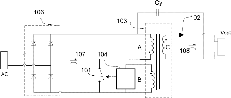
[0047] see Figure 5 , which is a schematic diagram of the transmission path of the common-mode current in the switching power supply.

[0048] For the switching power converter, the conducted interference of the EMI is tested by using a linear impedance stabilization network (LISN: Line Impedance Stabilization Network) 301 . The interference source generated by the equipment under test (EUT: Equipment Under Test) passes through the high-pass filter and 50Ω resistor inside the LISN to convert the interference current into a corresponding voltage value, which is analyzed by the receiver. The common mode interference in conducted interference is generally caused by the transient change of the voltage during the switching process. The transient c...


PUM


Abstract

The invention provides a method and transformer for reducing common-mode interference in a sandwich winding transformer. In the invention, a shield winding is respectively arranged between a secondary winding and adjacent windings to ensure that parasitic capacitance between a primary winding and the secondary winding can be reduced and a new path is provided for a common-mode current and the common-mode current is guided into ground (GND), therefore, the common-mode interference caused by the common-mode current can be reduced.

Description

technical field [0001] The invention relates to the technical field of sandwich-wound transformers, in particular to a method for reducing common-mode interference in a sandwich-wound transformer and a transformer. Background technique [0002] First introduce the sandwich winding method: when the transformer includes the primary winding and the secondary winding, the primary winding is divided into two halves, one half is wound on the outermost side, the other half is wound on the innermost side, and the secondary winding is wound in the middle; when the transformer includes the primary winding, When the secondary winding and auxiliary winding are used, the primary winding is divided into two halves in the same way, one half is wound on the outermost side, the other half is wound on the innermost side, and the secondary winding and auxiliary winding are wound in the middle. [0003] see figure 1 , which is a schematic diagram of a sandwich winding transformer in the prior ...

Claims


Application Information

Patent Timeline
Patent Type & Authority Applications(China)
IPC IPC(8): H01F27/28H01F27/30H01F27/36
Inventor 程增奇朱士海孙超群
Owner BCD SEMICON MFG
Why Eureka
Try Eureka