
Connection structure for electromagnetic switch draw bar and shifting fork of starter

A technology of electromagnetic switch and connection structure, applied in the direction of contact drive mechanism, etc., can solve the problem of no idle travel of the pull rod, and achieve the effect of eliminating idle travel, simple structure and low cost

Inactive Publication Date: 2011-11-02
陈锋光
View PDF0 Cites 0 Cited by
  • Summary
  • Abstract
  • Description
  • Claims
  • Application Information

AI Technical Summary

Problems solved by technology

[0003] In order to solve the idle travel caused by the power-off gap when the pull rod starts to move, the invention provides a connection structure between the pull rod and the shift fork of the electromagnetic switch, so that there is no idle travel when the pull rod starts to move

Method used


Image

  • Connection structure for electromagnetic switch draw bar and shifting fork of starter
  • Connection structure for electromagnetic switch draw bar and shifting fork of starter
  • Connection structure for electromagnetic switch draw bar and shifting fork of starter

Examples


Embodiment Construction

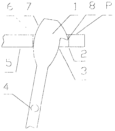
[0013] In the figure, 1. shift fork head, 2. pull rod out working surface, 3. shift fork head prior art pull out working surface, 4. shift fork pin, 5. pull rod, 6. pull rod push back list The working surface of the deflector, 7. Push back the working surface of the shift fork head, 8. The raised part of the shift fork head.

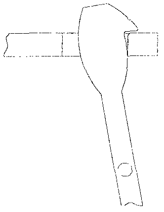
[0014] figure 1 , figure 2 In the first embodiment shown, the inside of the head of the pull rod (5) is a rectangular groove, the fork head (1) is sleeved in the rectangular groove, and the working surface of the raised portion (8) is the same as that of the prior art The working surfaces (3) are connected by a concave arc, and the concave arc does not contact the working surface (2) of the pull rod during the pulling process, and a plane P is above the working surface (2) of the pull rod. When the pull rod is in the initial position, there is no power-off gap between the working surface of the protruding part (8) of the shift fork head and the pull-out wo...


PUM


Abstract

The invention relates to a connection structure for an electromagnetic switch draw bar and a shifting fork of a starter, in particular to a connection structure capable of eliminating idle stroke when the draw begins to move. In the invention, a raised part is added on a shifting working face of the head part of the shifting fork on the basis of the prior art; no power-off gap exists between the raised part and the shifting working face of the draw bar; the starter works when the draw begins to move; and a plane is arranged above the shifting working face of the draw bar to ensure that the shifting working face of the draw bar keeps away from the raised part in the working process.

Description

Technical field [0001] The invention relates to a coupling structure of an electromagnetic switch pull rod of a starter and a shift fork, in particular to a coupling structure capable of eliminating the idle stroke when the pull rod starts to move. Background technique [0002] In the prior art, the electromagnetic switch of the starter is connected with the fork head through a pull rod, and controls the one-way device to engage and separate from the flywheel ring gear. The working surface on both sides of the shift fork head is a single arc, and there is always a power-off gap between the working surface of the electromagnetic switch pull rod. The existence of this gap causes an empty stroke when the pull rod starts to move, that is: the electromagnetic switch pull rod moves Remove the gap between the dial out surfaces before turning the unidirectional device. After the one-way device is pulled out, the dial out surface of the shift fork and the pull rod fit together, but there...

Claims


Application Information

Patent Timeline
Patent Type & Authority Applications(China)
IPC IPC(8): H01H3/46
Inventor 陈锋光
Owner 陈锋光
Learn More