Voltage quality control (VQC) system based on static var generator(SVG) and method thereof

An automatic control system, voltage and reactive power technology, applied in the direction of reactive power adjustment/elimination/compensation, reactive power compensation, etc., can solve problems such as easy oscillation, capacitance and reactance cannot be switched frequently, transformers cannot be frequently shifted up and down, etc. , to achieve the effect of improving the response speed

Inactive Publication Date: 2011-11-02
SIEYUAN QINGNENG ELECTRICAL & ELECTRONICS
View PDF9 Cites 29 Cited by
  • Summary
  • Abstract
  • Description
  • Claims
  • Application Information

AI Technical Summary

Problems solved by technology

[0008] 1. The voltage and reactive power cannot be continuously adjusted: the control objects included in the above control system are capacitor banks, reactor banks and transformers. The voltage changes according to the gear position, and the reactive power varies discretely according to the capacitance or reactance capacity. The voltage and reactive power cannot be continuously adjusted. No use;
[0009] 2. The response speed is not fast enough: In order to ensure the stability of the control and prolong the service life of the equipment, it is usually required that the capacitor and reactance cannot be switched frequently, and the transformer cannot be frequently shifted up and down, and there must be a certain operating time interval. Any device within the interval can no longer perform actions
[0010] 3. Generally, the nine-zone map, the seventeen-zone map or their improved methods are used. When the control strategies of each zone are different, this method is easy to adjust the control back and forth at the boundary of each zone, and is prone to oscillation

Method used


Image

  • Voltage quality control (VQC) system based on static var generator(SVG) and method thereof
  • Voltage quality control (VQC) system based on static var generator(SVG) and method thereof
  • Voltage quality control (VQC) system based on static var generator(SVG) and method thereof

Examples


Embodiment

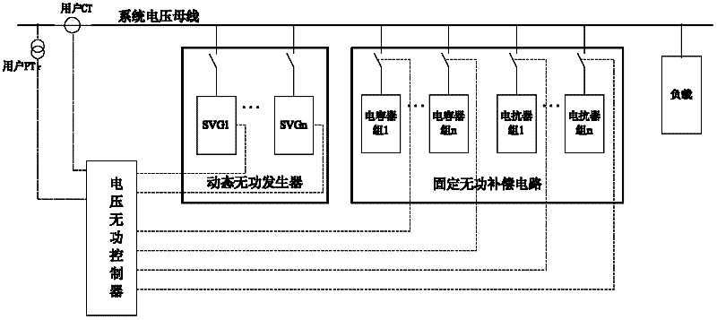
[0023] Such as figure 1 As shown, this embodiment includes: a dynamic reactive power generator, an automatic voltage reactive power controller and a fixed reactive power compensation circuit, wherein: several groups of dynamic reactive power generators are connected in parallel to the system voltage bus, and dynamically output continuously according to the control command Capacitive reactive power or inductive reactive power; several groups of fixed reactive power compensation circuits are connected in parallel on the system voltage bus, input or exit according to the control command, and output capacitive reactive power or inductive reactive power of fixed size; automatic control of voltage reactive power The input terminals of the controller are respectively connected to the user PT and the user CT to collect the voltage and current signals required for control, and the output terminals of the voltage reactive power automatic controller are respectively connected to the dynam...


PUM


Abstract

The invention provides a voltage quality control (VQC) system based on a static var generator (SVG) and a method thereof in the voltage reactive power integration control technical field. The system comprises dynamic reactive power generators, a voltage reactive power automatic controller and fixed reactive compensation circuits. A plurality of dynamic reactive power generators and a plurality offixed reactive compensation circuits are in parallel connection to connect with a bus connecting with an output terminal of an electric power system transformer, and output continuous capacitive reactive power and induction reactive power dynamically. An input terminal of the voltage reactive power automatic controller is connected with the dynamic reactive power generators and the fixed reactivecompensation circuits respectively and outputs a control instruction. According to the invention, speed of static var integration controlled by the voltage quality control is raised.

Description

technical field [0001] The invention relates to a method in the technical field of voltage and reactive power comprehensive control, in particular to a voltage and reactive power automatic control (VQC) system and method based on a dynamic var generator (SVG). Background technique [0002] SVG (Static Var Generator, Static Var Generator) is a reactive power compensation device that has developed rapidly in recent years. Sexual reactive power and perceptual reactive power. [0003] As the new dynamic var generator SVG is widely used in the on-site reactive power compensation of the power grid, it is necessary to combine the fast SVG device and the traditional VQC device for coordinated control to ensure that the regulation goals are consistent. [0004] After searching the existing technology, it is found that Chinese patent document number CN2678227, published on 2005-2-9, records a voltage and reactive power automatic control device, which includes a detection and control ...

Claims


Application Information

Patent Timeline
Patent Type & Authority Applications(China)
IPC IPC(8): H02J3/18
CPCY02E40/30
Inventor 赵香花陈远华路永辉鲁闯李小兵
Owner SIEYUAN QINGNENG ELECTRICAL & ELECTRONICS
Why Eureka
Try Eureka