Device for adjustment of a rotor blade, wind energy converter, and method for adjusting a rotor blade

A technology for wind energy converters and wind rotor blades, which is applied in wind energy generation, control of wind turbines, wind turbines, etc., can solve problems such as excessive wind energy converters and damage loads.

Active Publication Date: 2011-11-02
美国超导奥地利有限公司
View PDF9 Cites 8 Cited by
  • Summary
  • Abstract
  • Description
  • Claims
  • Application Information

AI Technical Summary

Problems solved by technology

Although the rotor blades may eventually reach the feathered position in this way, a considerable number of rotations of the rotor may be required during which the wind energy converter is subjected to excessive and possibly is a destructive load

Method used


Image

  • Device for adjustment of a rotor blade, wind energy converter, and method for adjusting a rotor blade
  • Device for adjustment of a rotor blade, wind energy converter, and method for adjusting a rotor blade
  • Device for adjustment of a rotor blade, wind energy converter, and method for adjusting a rotor blade

Examples


Embodiment Construction

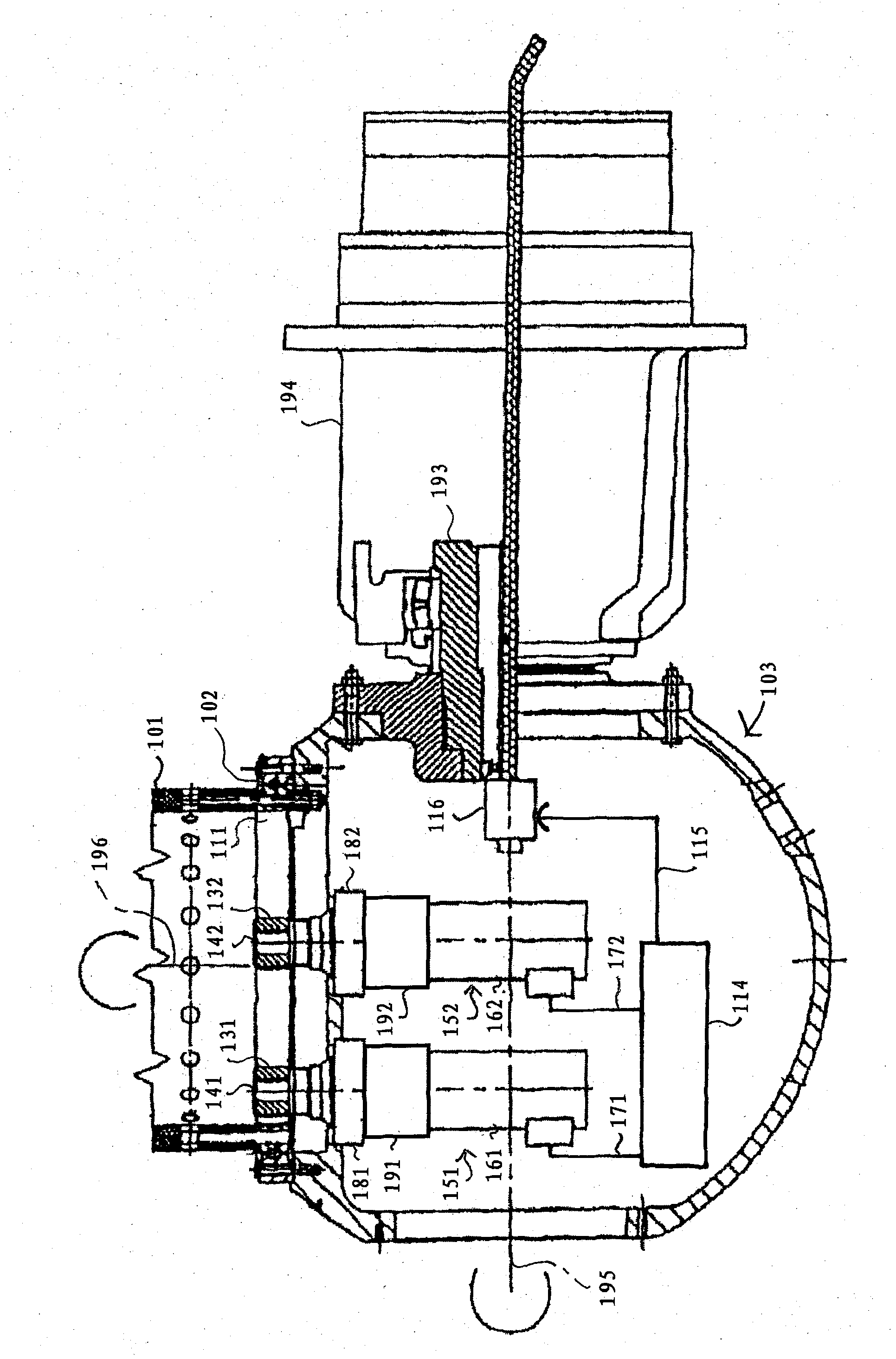
[0041] figure 1 A cross-sectional view of a rotor hub 103 is shown which is held rotatably about a rotor axis 195 in a rotor bearing 193 of a wind energy converter. In the particular hub shown, the rotor bearing 193 is mounted in a nacelle 194 (partially shown) which itself is held rotatably on top of the tower. One rotor blade 101 is attached to the inner ring of a pivot bearing 102 whose outer ring is screwed to the rotor hub 103 . For clarity, only the rotor blade 101 is drawn. However, wind energy converters usually comprise more than one rotor blade 101 , and generally three rotor blades.

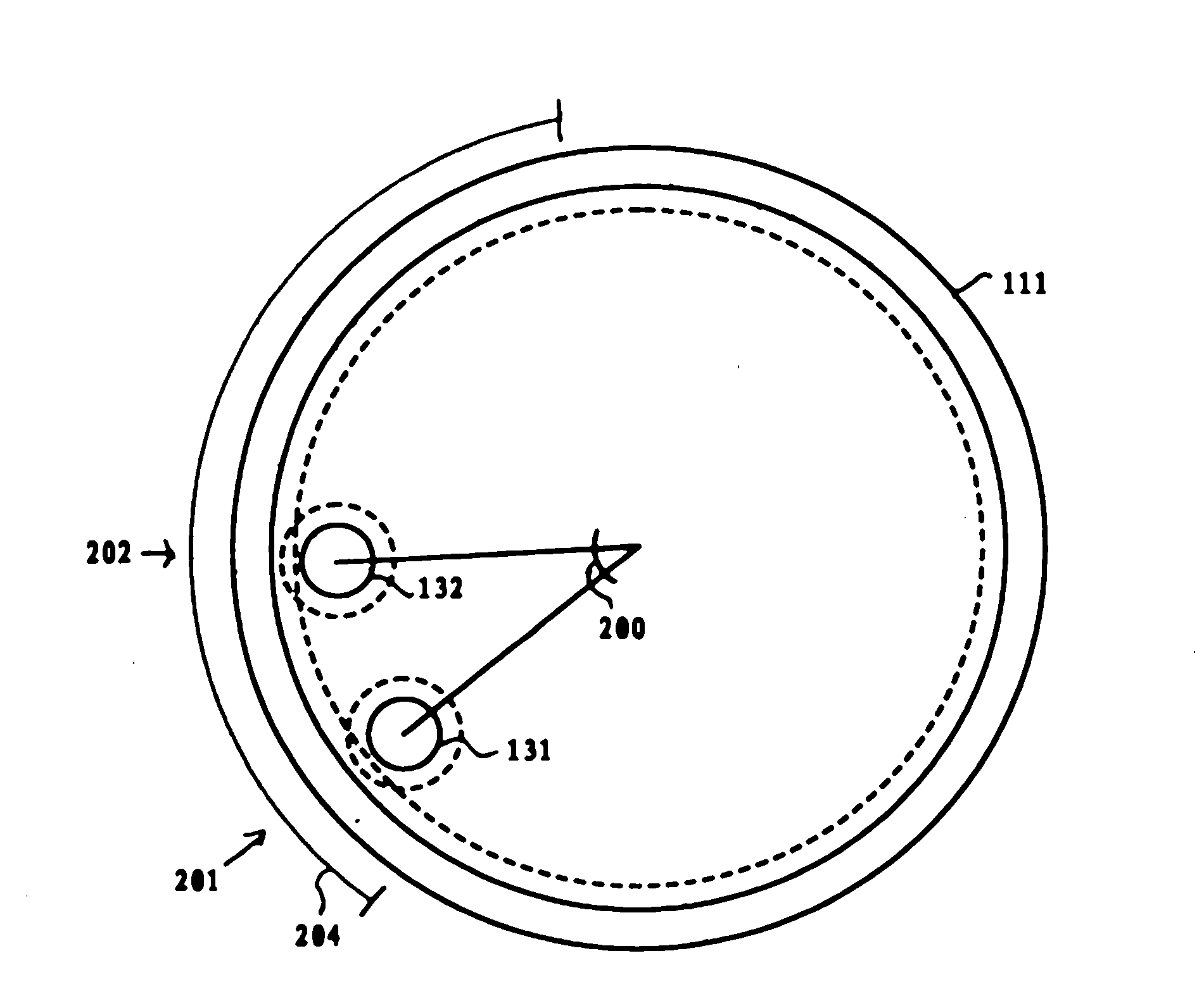
[0042] The rotor blade 101 is attached to a pivot bearing 102 with internal teeth 111 forming a circular gear. The pivot bearing 102 rotatably holds the rotor blade 101 about a blade rotation axis 196 which is slightly inclined with respect to the longitudinal direction (not shown) of the rotor blade 101 such that the center of gravity of the rotor blade is outside the blade rotatio...


PUM


Abstract

Some general aspects of the invention provide a device (151, 152, 114) for adjustment of a pivotally mounted rotor blade (101) of a wind energy converter. The device comprises a first drive (151) and a second drive (152) that cooperate to turn the rotor blade (101) between an operating position and a feathered position. The device further comprises a first activatable lockout (191) connected to the rotor blade (101), which in an activated state prevents turning of the rotor blade (101) into the operating position, but allows turning of the rotor blade (101) into the feathered position. Under further aspects, the invention provides a wind energy converter comprising the device (151, 152, 114) and a method for adjusting a rotor blade (101), which is pivotally mounted on a rotor hub (103) of the wind energy converter.

Description

Background technique [0001] The invention relates to a device for adjusting a rotor blade mounted on a rotor hub of a wind energy converter, a corresponding method for adjusting a rotor blade of a wind energy converter, and a wind energy converter. [0002] Wind energy can be converted into a useful form, such as electricity, by a wind energy converter, which typically includes a generator driven by a wind rotor, such as a low-speed propeller rotor rotatably supported at the upper end of a tower. wheel. Generally, a rotor includes a centrally located rotor hub and at least one rotor blade extending radially from the rotor hub. [0003] Wind energy converters are subjected to high stresses due to wind forces. One way to reduce the forces acting on the wind energy converter is to use rotor blade regulation, where the rotor blades are rotationally attached to the rotor hub such that each blade can move about the axis of rotation approximately in the longitudinal direction of th...

Claims


Application Information

Patent Timeline
Patent Type & Authority Applications(China)
IPC IPC(8): F03D7/02F03D11/00
CPCF03D11/00F05B2260/76Y02E10/72F05B2270/602Y02E10/723F05B2260/78Y02E10/722F03D7/0224F05B2260/79F03D15/10F03D80/00F05B2270/328
Inventor 安东·沃尔夫
Owner 美国超导奥地利有限公司
Why Eureka
Try Eureka