Mesh belt type air energy dryer

An air energy drying and air energy technology, which is applied in dryers, progressive dryers, drying and other directions, can solve the problems of uneven air volume and temperature distribution, unstable drying temperature, and poor product quality. The effect of reducing heat source supply cost, improving drying effect and improving heat energy utilization rate

Pending Publication Date: 2021-05-07
四川华景智农农业开发有限责任公司
View PDF0 Cites 1 Cited by
  • Summary
  • Abstract
  • Description
  • Claims
  • Application Information

AI Technical Summary

Problems solved by technology

[0004] The invention provides a mesh belt type air energy dryer to solve the problem that the hot air in the drying room loses heat to form cold air. The hot air near the air duct has a large air volume and high temperature. As the distance increases, the hot air volume gradually Decrease, the temperature gradually decreases, causing the overall air volume and temperature distribution in the drying room to be uneven, the temperature passing through the surface of the material is fluctuating, and the unstable drying temperature leads to poor drying effect and poor product quality.

Method used


Image

  • Mesh belt type air energy dryer
  • Mesh belt type air energy dryer
  • Mesh belt type air energy dryer

Examples


Embodiment 1

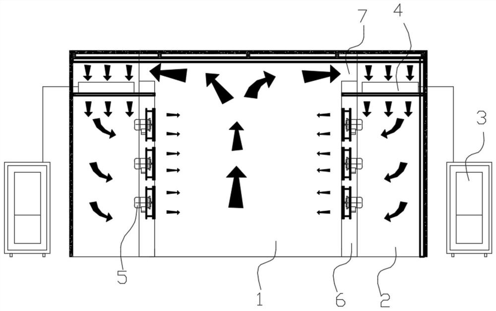
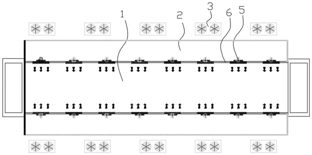
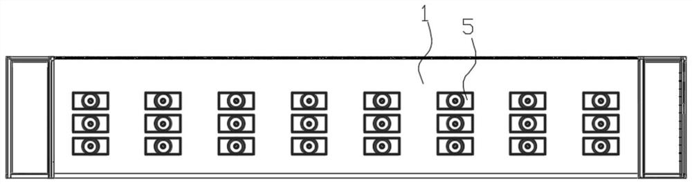
[0030] like figure 1 , figure 2 and image 3 As shown, a mesh belt type air energy dryer includes a drying chamber 1, an air chamber 2, an air energy host 3, an air energy condenser 4 and an axial flow fan 5, and the air chambers are arranged symmetrically on both sides of the drying chamber 1. 2. The drying chamber 1 and the air chamber 2 are separated by a partition 6, and the top of the air chamber 2 is provided with an air energy condenser 4, and the air energy condenser 4 is connected to the air energy host 3 arranged outside the air chamber 2;

[0031] A number of through holes are provided on the partition 6, and the through holes are distributed in a rectangular array. The through holes of the partitions 6 on both sides are symmetrically arranged, and the axial flow fan 5 is installed in the through holes, so that the air chamber can be blown by the axial flow fan 5. The hot air in 2 is accelerated to the drying chamber 1;

[0032] The top of the partition 6 is pro...

Embodiment 2

[0042] Embodiment 2 is a further optimization of Embodiment 1.

[0043] like Figure 4As shown, the drying chamber 1 is provided with a fixed mount 12. There are at least two fixed mounts 12. The mounting plate 13 that is slidably connected, that is, the mounting plate 13 slides up and down on the fixed frame 12, and the mounting plate 13 is connected with the horizontal conveying chain 10.

[0044] There are multiple mounting plates 13, and the multiple mounting plates 13 are distributed up and down on the fixed frame 12, and the mounting plates 13 are slidably connected with the horizontal conveying chain 10. The mounting plate 13 is provided with a driving device, which is connected to the horizontal conveying chain 10 , and the driving device is used to drive the horizontal conveying chain 10 to move left and right relative to the mounting plate 13 . The driving device is a hydraulic cylinder or an air cylinder.

[0045] The fixed frame 12 is provided with a driving dev...


PUM


Abstract

The invention provides a mesh belt type air energy dryer. The mesh belt type air energy dryer comprises a drying chamber, air chambers, air energy main machines, air energy condensers and axial flow fans, wherein the air chambers are symmetrically arranged on the two sides of the drying chamber, the drying chamber and the air chambers are separated through partition plates, the air energy condensers are arranged at the tops of the air chambers, and the air energy condensers are connected with the air energy main machines arranged outside the air chambers. A plurality of through holes are formed in each partition plate, the through holes are distributed in a rectangular array mode, the through holes in the partition plates on the two sides are symmetrically formed, and the axial flow fans are installed in the through holes. An opening is formed in the top of each partition plate, a cold air inlet of each air energy condenser faces upwards, and a hot air outlet of each air energy condenser faces downwards. The problems that in the prior art, the overall air volume and temperature distribution in a drying chamber is not uniform, the temperature of the air passing by the surfaces of materials is in a wavy state, the drying temperature is unstable, so that the drying effect is poor, and the product quality is poor are solved.

Description

technical field [0001] The invention relates to the technical field of drying equipment, in particular to a mesh belt air dryer. Background technique [0002] Mesh belt dryer is a batch and continuous production of electric heating, steam heating and hot air heating, which uses steel mesh as a conveyor belt to carry materials for continuous drying. The mesh belt dryer mainly transports the finished product directly to the flat conveyor through the conveyor, and evenly distributes the finished product on the dryer through the scraper on the upper end of the flat conveyor to improve the air permeability and achieve the drying effect. Mesh belt dryer is a commonly used continuous drying equipment. It can be widely used in building materials, electronics and other industries. It is especially suitable for drying flake, strip and granular materials with good air permeability. The material can also be dried after being shaped by a granulator or extruder. [0003] In the existing...

Claims


Application Information

Patent Timeline
Patent Type & Authority Applications(China)
IPC IPC(8): F26B15/18F26B21/00F26B21/04F26B25/00F26B25/08
CPCF26B15/18F26B21/002F26B21/004F26B21/04F26B25/001F26B25/08
Inventor 陈俊年项聪何攀熊丽谯延海任强蒋玮
Owner 四川华景智农农业开发有限责任公司
Why Eureka
Try Eureka