Air pipe and fan system

A fan system and air duct technology, applied in mechanical equipment, machines/engines, liquid fuel engines, etc., can solve problems such as uneven air output and large gas energy loss, and achieve the effect of increasing transmission efficiency

Pending Publication Date: 2018-01-19
CHONGQING GENERAL IND (GRP) LTD
View PDF0 Cites 3 Cited by
  • Summary
  • Abstract
  • Description
  • Claims
  • Application Information

AI Technical Summary

Problems solved by technology

Due to the air duct in the prior art has a certain angle, the gas loses a

Method used


Image

  • Air pipe and fan system
  • Air pipe and fan system
  • Air pipe and fan system

Examples


Embodiment 1

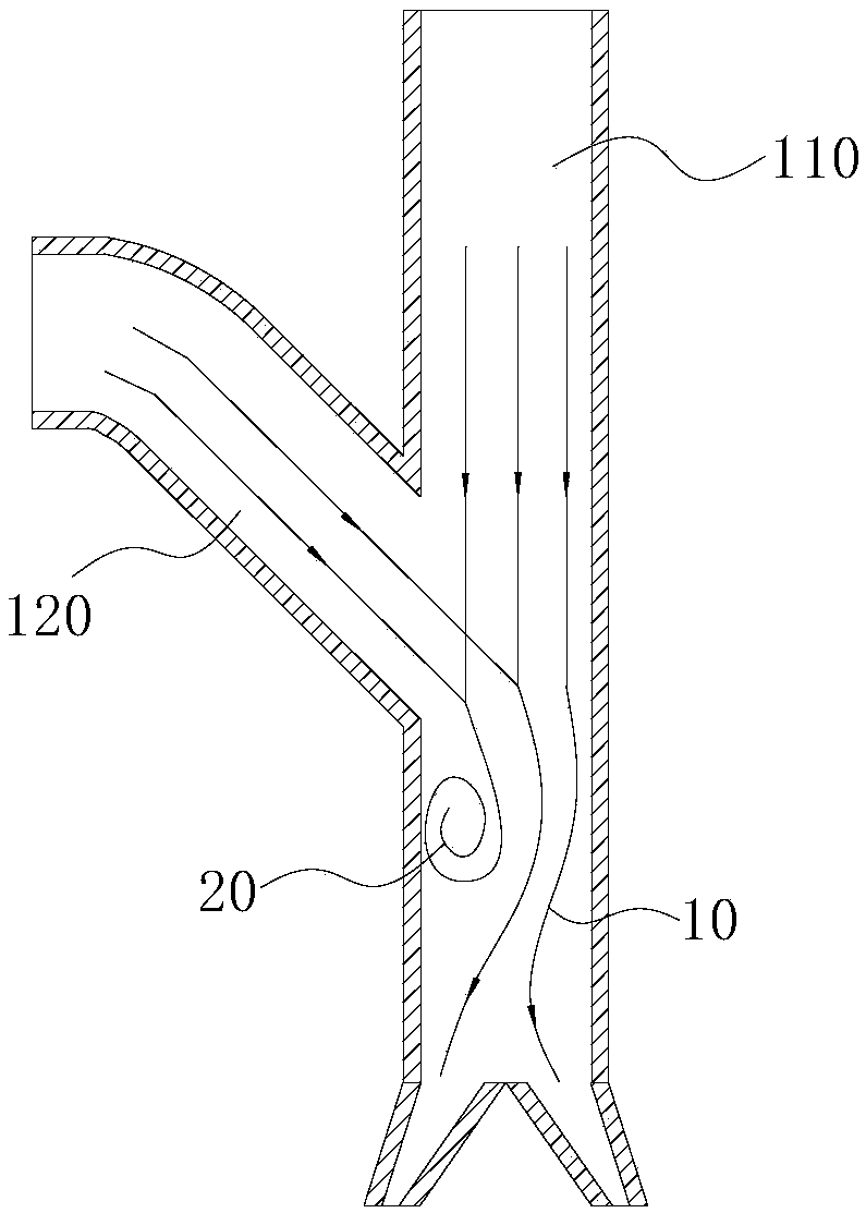
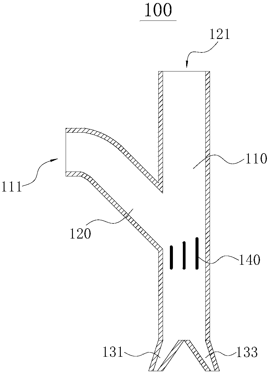
[0047] refer to figure 2 , the figure shows an air duct 100 provided in this embodiment, which includes a first duct body 110 and a second duct body 120 that are connected to each other and are not collinear. An end of the first pipe body 110 away from the second pipe body 120 is an air outlet, and an end of the second pipe body 120 away from the first pipe body 110 is a first air inlet 111 .

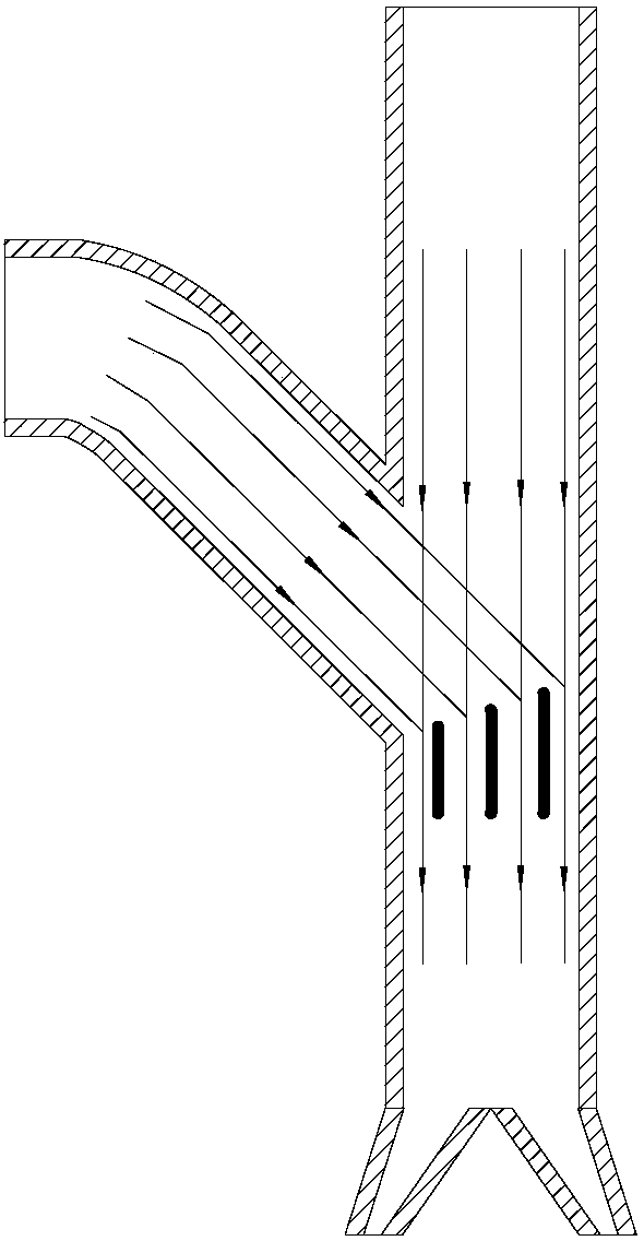
[0048] In use, the gas passes through the first pipe body 110 and the second pipe body 120 in turn. Since the connection between the first pipe body 110 and the second pipe body 120 is at a certain angle, in order to avoid vortices, it will cause energy loss and air outlet pressure. Poor phenomenon, so a deflector 140 is provided at the connection between the second pipe body 120 and the first pipe body 110, through the deflector 140, the gas flows from the first pipe body 110 to the second pipe body 120 caused by the angle Swirl and turbulence for increased gas transfer efficiency. ...


PUM


Abstract

The invention relates to the field of fans, in particular to an air pipe and a fan system. The air pipe comprises a first pipe body and a second pipe body, which communicate with each other and are non-collinear. Gas passes through the first pipe body and the second pipe body in sequence; and as the connecting place of the first pipe body and the second pipe body forms a certain angle, in order toprevent the phenomenon of swirls, energy loss and exhaust pressure difference, a guide plate is arranged in the communicating place of the second pipe body and the first pipe body for removing the swirls and turbulent currents caused by the angle when the gas flows from the first pipe body to the second pipe body, and the gas transmission efficiency is improved. The invention further provides thefan system; and the fan system comprises a centrifugal ventilator and the air pipe. An exhaust port of the air pipe communicates with the centrifugal ventilator for providing stable and uniform air volume to the centrifugal ventilator. The fan system is high in working efficiency and low in energy loss.

Description

technical field [0001] The invention relates to the field of fans, in particular to an air duct and a fan system. Background technique [0002] The fan is a machine that relies on the input mechanical energy to increase the gas pressure and discharge the gas. It is a driven fluid machine. Fan is the customary abbreviation for gas compression and gas conveying machinery in China. Generally speaking, fans include ventilators, blowers, and wind generators. Fans are widely used in ventilation, dust removal and cooling of factories, mines, tunnels, cooling towers, vehicles, ships and buildings, ventilation and induction of boilers and industrial furnaces; cooling and ventilation in air conditioning equipment and household appliances ; Grain drying and selection, wind tunnel wind source and inflation and propulsion of hovercraft, etc. [0003] As a part of the fan, the air duct is mainly used to supply air to the fan. Due to the air duct in the prior art has a certain angle, th...

Claims


Application Information

Patent Timeline
IPC IPC(8): F04D25/08F04D29/44F04D29/00
CPCF04D25/08F04D29/00F04D29/44
Inventor 周红候海臣满超
Owner CHONGQING GENERAL IND (GRP) LTD
Why Eureka
Try Eureka