Rudderstock for ground transmission machine operated by rudderstock

A technology for ground conveying and rudder stock, applied in the direction of motor vehicles, transportation and packaging, lifting devices, etc., can solve the problems of undesired ergonomics, different operating characteristics, etc.

Active Publication Date: 2015-04-08
斯蒂尔公司
View PDF5 Cites 0 Cited by
  • Summary
  • Abstract
  • Description
  • Claims
  • Application Information

AI Technical Summary

Problems solved by technology

Furthermore, changes in the swing characteristics of the tiller head in the two attitudes of the tiller lead to undesired ergonomics and different operating characteristics

Method used


Image

  • Rudderstock for ground transmission machine operated by rudderstock
  • Rudderstock for ground transmission machine operated by rudderstock
  • Rudderstock for ground transmission machine operated by rudderstock

Examples


Embodiment Construction

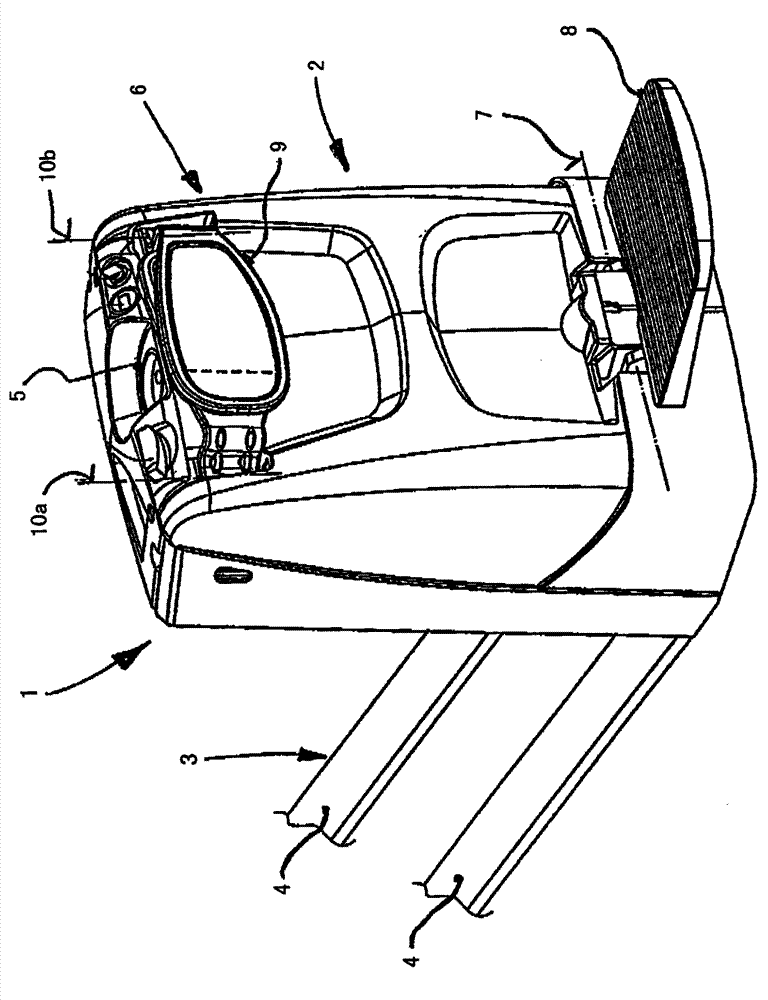
[0039] exist figure 1 10 shows a tiller-operated floor conveyor machine 1 according to the invention in the form of a storage technology palletizer, which is designed, for example, as a lift truck, in particular as a low-travel lift truck. The floor conveyor 1 has a drive part 2 and a load part 3 that can be raised or lowered relative to the drive part 2 . The drive part 2 comprises a load fork formed, for example, from two load arms 4 spaced apart laterally.

[0040] The load part 3 is supported on the track by means of load wheels which are arranged on the tips of the load arms 4 and are not shown in detail.

[0041] A traction drive unit (not shown in detail) is arranged in drive 2 pivotable about a vertical pivot axis, said traction drive unit comprising a drive wheel and a traction drive motor driving the drive wheel. The operator uses the figure 1 The floor conveyor 1 is actuated and steered by a tiller, not shown in detail, which is arranged on the upper side of the ...


PUM


Abstract

The shaft has a shaft base (16), a shaft piston (18) and a shaft head (20), where the shaft is pivotally supported around a vertical pivot axis (17) by the shaft base at a drive part of an industrial truck. A pivot joint (25) is formed between a shaft base-closed part (18a) and a shaft head-closed part (18b) by a bearing block (30). The bearing block is coupled with the shaft base over a parallel guiding unit (31). The shaft head-closed part is pivotally supported at the bearing block around the horizontal pivot axis (26). An independent claim is also included for a shaft-guided industrial truck with a driver stand platform.

Description

technical field [0001] The present invention relates to a rudder stock operated ground conveying machinery, in particular a rudder stock for lift trucks, the rudder stock comprising a rudder foot, a rudder handle and a rudder head, wherein the rudder stock can surround a substantially vertical A straight pivot axis is pivotally supported on the drive of the floor conveyor by means of the tiller foot, which is designed as a tiltable tiller for length adjustment, wherein the tiller shank has A two-piece structure having a part near the rudder foot and a part near the rudder head, wherein the part near the rudder foot is pivotably supported about a substantially horizontal pivot axis On the tiller foot and the part near the tiller head is supported on the region near the tiller foot via a pivot joint with an essentially horizontal pivot axis. Background technique [0002] Tiller-operated ground handling machines are known as lift trucks, in particular low-stroke lift trucks or...

Claims


Application Information

Patent Timeline
Patent Type & Authority Patents(China)
IPC IPC(8): B66F9/20
CPCB62D51/02B62D51/001B66F9/07568B66F9/20B62B5/064B62B3/0612B62B5/063
Inventor A·维登特
Owner 斯蒂尔公司
Why Eureka
Try Eureka