Actuating device for an electrical connection terminal

A control device and electric wiring technology, which is applied to the parts of the connection device, coupling device, conductive connection, etc., can solve the problems of large and cumbersome button design, and achieve the effect of low cost, avoiding damage, and reliable operation

Active Publication Date: 2011-11-09
WAGO VERW GMBH
View PDF5 Cites 37 Cited by
  • Summary
  • Abstract
  • Description
  • Claims
  • Application Information

AI Technical Summary

Problems solved by technology

In order to achieve an effective leverage arm, the ove

Method used


Image

  • Actuating device for an electrical connection terminal
  • Actuating device for an electrical connection terminal
  • Actuating device for an electrical connection terminal

Examples


Embodiment Construction

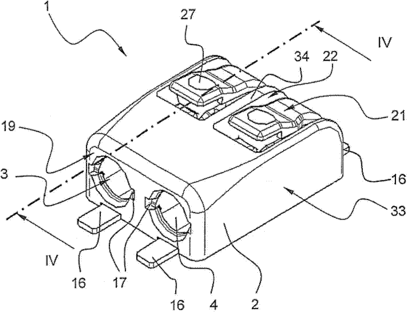
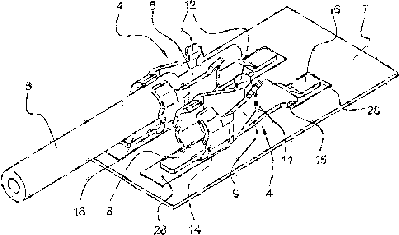
[0023] figure 1 The electrical terminal 1 according to the invention is shown with an insulating material housing 2 in which a metallic contact frame 4 is accommodated. The housing 2 of insulating material has at least one on the end face 19 for inserting an electrical lead 5 (see Figure 4 ) leads into the opening 3. In the exemplary embodiment shown, the terminal block 1 is designed with two terminals, each with a conductor entry opening 3 and a contact frame 4 . However, the terminal clip can also have any other desired number of terminals.

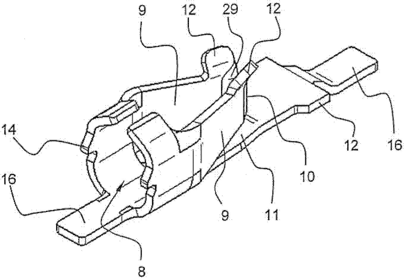
[0024] exist figure 1 The contact area 16 of the contact frame 4 can also be seen in the figure, which contacts the corresponding contact section 28 (eg conductor track) of the printed circuit board 7 (see figure 2 ). In this case, the contact region 16 is in particular connected by soldering (soldering connection of surface mount components: ) is connected to the contact section 28, but a plug connection is also conceivable. ...


PUM


Abstract

Actuating device for an electrical connection terminal (1), wherein the electrical connection terminal comprises a contact frame (4), arranged in a housing (2) made of insulating material, with a conductor terminal connection for an electrical conductor (5), and the actuating device comprises an actuating element in the form of a pusher (21) which is integrally connected to the housing made of insulating material, and wherein the conductor terminal connection is formed on the contact frame by at least one spring element (9), the free end of which forms a clamping edge (10) which is directed toward the electrical conductor (5) and to which a clamping force is applied, and the conductor terminal connection can be opened by action of the pusher on the at least one spring element by a force being applied to the spring element by the pusher counter to the clamping force. According to the invention, the pusher consists of a pusher arm (23), wherein the pusher arm is connected with one of its ends to the housing made of insulating material, and wherein the pusher arm extends along at least a partial section of two upper surfaces (18, 20) of the housing made of insulating material which are arranged at an angle to each other.

Description

technical field [0001] The invention relates to an actuating device for an electrical terminal clamp, wherein the electrical terminal clamp comprises a contact frame arranged in a housing of insulating material, the contact frame having wire clamping connections for electrical conductors, and the actuating device comprising a An actuating element designed as a button, which is integrally connected to the housing of insulating material, and wherein the conductor clamping joint on the contact frame is formed by at least one spring element, the free end of which forms a pointing electrical conductor and is formed by The clamping edge is loaded with clamping force and the conductor clamping connection can be opened by the action of the button on at least one spring element in such a way that a force counteracting the clamping force is exerted on the spring element by the button . Background technique [0002] ES 2 159 247 A1 shows an electrical terminal clamp with a housing for...

Claims


Application Information

Patent Timeline
IPC IPC(8): H01R13/629H01R13/46H01R13/02H01R4/48
CPCH01R4/48H01R12/57H01R12/53H01R13/02H01R13/193H01R13/46H01R13/629H01R4/48185H01R12/515H01R4/48455H01R4/48365H01R13/50H01R9/24
Inventor 亨里克·比斯斯蒂芬·加索尔
Owner WAGO VERW GMBH
Why Eureka
Try Eureka