Electrical machine and a method for assembling it

A machine, electric technology used in the field of assembling electric machines

Active Publication Date: 2011-11-09
THE SWITCH DRIVE SYSTEMS OY +1
View PDF7 Cites 4 Cited by
  • Summary
  • Abstract
  • Description
  • Claims
  • Application Information

AI Technical Summary

Problems solved by technology

Mounting the permanent magnets in the correct position in the rotor is a challenging task due to the forces induced by the permanent magnets

Method used


Image

  • Electrical machine and a method for assembling it
  • Electrical machine and a method for assembling it
  • Electrical machine and a method for assembling it

Examples


Embodiment Construction

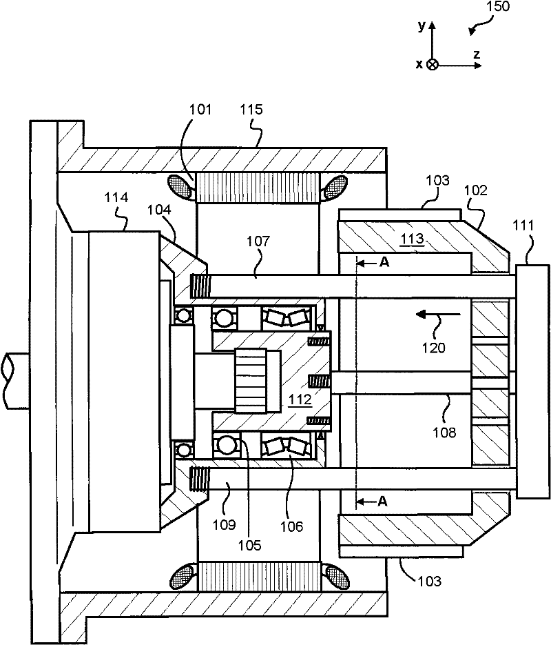
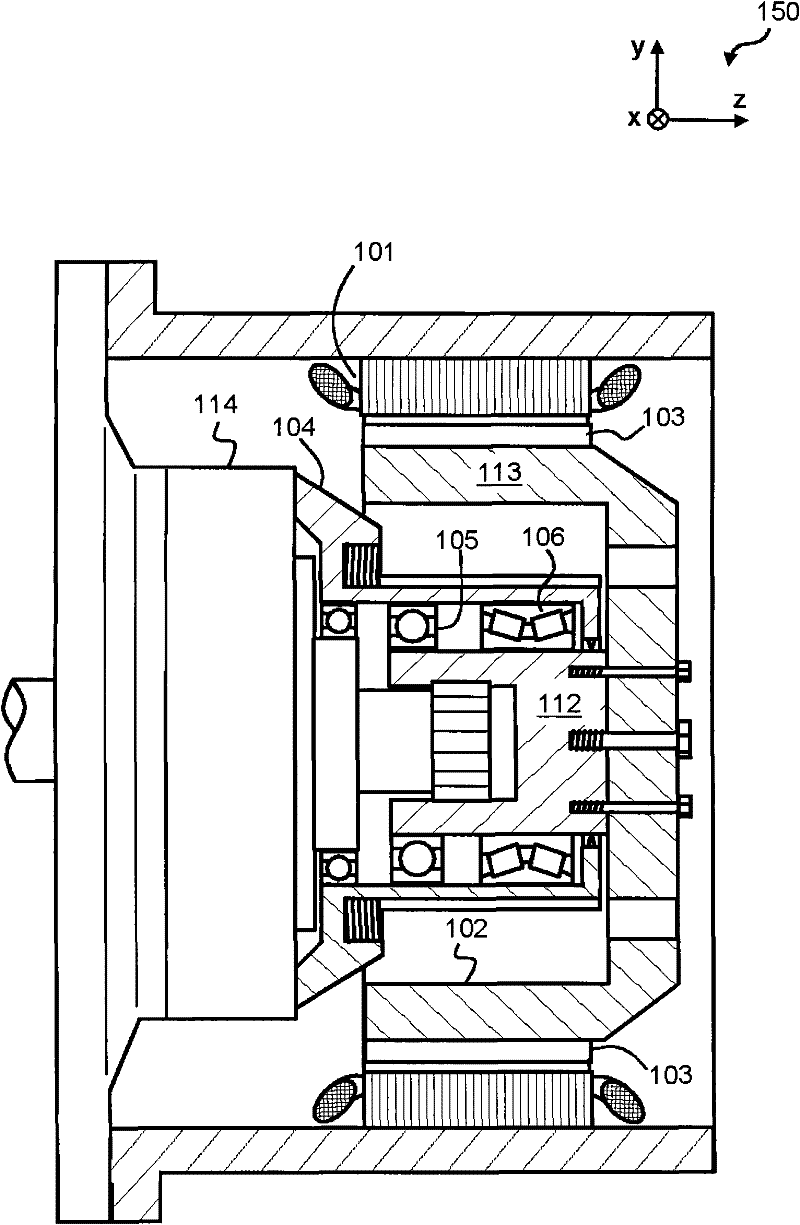
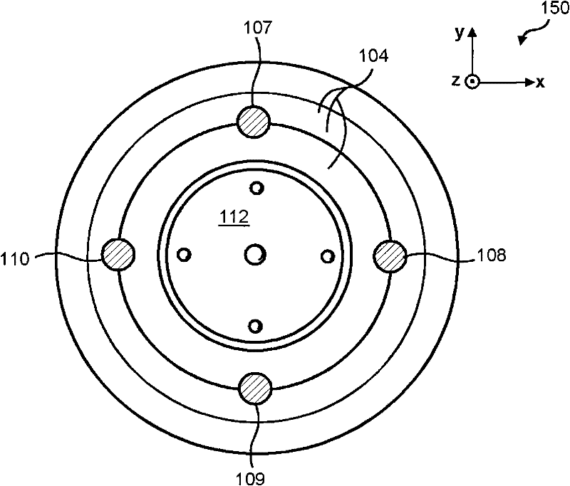
[0030] Figure 1a shows a schematic cross-sectional view of an electric machine according to an embodiment of the invention in a condition in which the rotor is being installed, and Figure 1b A schematic cross-sectional view of the electric machine is shown in a condition where the rotor is in its final position. Figure 1c showing along Figure 1a A view of a section taken along the line A-A shown. exist Figure 1a-1c In , the axial direction is the direction of the z-axis of the coordinate system 150 . The electric machine comprises a stator 101 comprising a laminated stator core and stator windings. The rotor 102 of the electric machine comprises a frame 113 and permanent magnets 103 attached to the frame 113 . The electric machine comprises a mechanical support structure 104 comprising bearings 105 and 106 arranged as in Figure 1b Support the rotor relative to the stator when the rotor is shown in its usual position. exist Figure 1a-1c In the exemplary configurati...


PUM


Abstract

A method for installing a rotor of an electrical machine and an electrical machine are disclosed. The method comprises using axially directed guide bars (107-109) for keeping the rotor (102) centered with respect to a bore of a stator (101) during the installation of the rotor. The rotor has sliding surfaces so that it can be slid in the axial direction to its final position along the guide bars. The mechanical support structure (104) that supports bearings (105, 106) of the rotor are provided with supporting surfaces for being able to give mechanical support to the guide bars. The mechanical support structure (104) may comprise for example threaded holes to which threaded ends of the guide bars can be tightened. After the rotor has been moved to its final position and it is supported by the bearings, the guide bars are removed.

Description

technical field [0001] The invention relates to an electric machine and a method for assembling an electric machine. More specifically, the method involves mounting a rotor of an electric machine into a bore of a stator of the electric machine. Background technique [0002] It may sometimes be necessary to assemble or repair an electric machine at its usual operating site, ie in field conditions. For example, there may be situations where eg bearings of an electric machine have to be changed and it may be too cumbersome and / or expensive to move the entire electric machine for repair elsewhere. In particular, fitting the rotor of an electric machine into the inner bore of the stator core in field conditions can be a cumbersome task. In particular, assembling permanent magnet electric machines can be a challenging task even in a workshop situation because of the strong forces induced by the permanent magnets that make fitting the rotor, including the permanent magnets, into ...

Claims


Application Information

Patent Timeline
Patent Type & Authority Applications(China)
IPC IPC(8): H02K5/16H02K15/00H02K15/03
CPCH02K15/03H02K1/30H02K15/16H02K5/1735Y10T29/49009Y10T29/49012H02K15/02
Inventor 图奥马斯·沃莱-阿皮亚拉约尔马·蒂尔科宁维莱·帕卡里宁亚里·托伊卡宁奥林·柳科宁约尔马·穆斯塔拉赫蒂伊尔卡·马蒂凯宁
Owner THE SWITCH DRIVE SYSTEMS OY
Why Eureka
Try Eureka