Magnetic resonance imaging device and synchronous imaging method

A technology of magnetic resonance imaging and synchronous measurement, which is applied in magnetic resonance measurement, measurement using nuclear magnetic resonance imaging system, and measurement devices, etc., can solve the problem of prolonging the imaging time and achieve the effect of shortening the imaging time

Inactive Publication Date: 2011-11-09
HITACHI LTD
View PDF5 Cites 9 Cited by
  • Summary
  • Abstract
  • Description
  • Claims
  • Application Information

AI Technical Summary

Problems solved by technology

In this way, although the influence of turbulent blood flow is eliminated, the echo signal in a stable blood flow state is measured, which improves the contrast of the reconstructed image, but because the pulse sequence is repeated every fixed number of heartbeats , so the problem of the so-called extended shooting time remains unresolved

Method used


Image

  • Magnetic resonance imaging device and synchronous imaging method
  • Magnetic resonance imaging device and synchronous imaging method
  • Magnetic resonance imaging device and synchronous imaging method

Examples


no. 1 approach

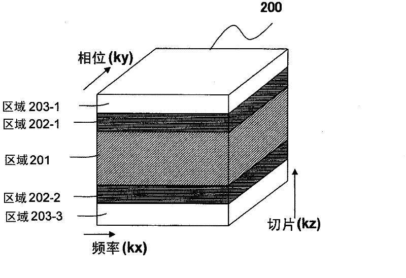
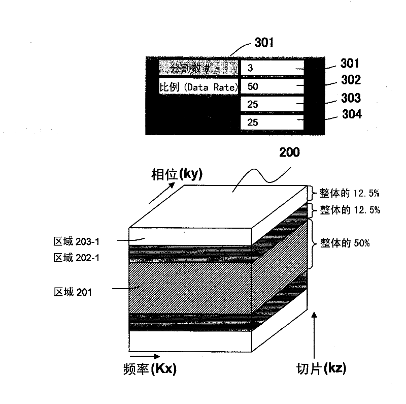
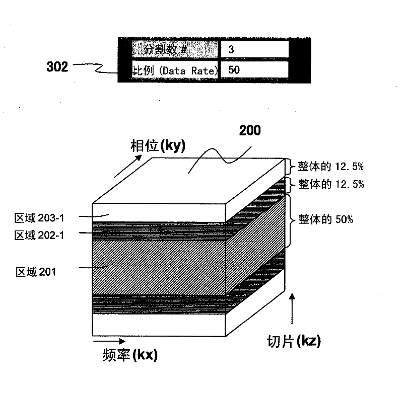
[0073] Next, a first embodiment of the MRI apparatus and the synchronous imaging method of the present invention will be described. In this embodiment, a delay time is set between the trigger information and the measurement period of the echo signal as the first period, and the ratio of the delay time in the measurement of the echo signal corresponding to the partial region on the high spatial frequency side to that of the low spatial frequency The delay time in the measurement of the echo signal corresponding to the partial region on the frequency side is short. This embodiment is suitable for acquiring, for example, a T1-emphasized image. Below, based on Figure 5 ~ Figure 7 This embodiment will be described.

[0074] First, use Figure 5 The outline of this embodiment will be described. Figure 5 An example of synchronous electrocardiographic measurement according to the present embodiment is shown in which an electrocardiographic waveform of a subject is detected and t...

no. 2 approach

[0101]Next, a second embodiment of the MRI apparatus and the simultaneous imaging method of the present invention will be described. In this embodiment, the waiting time from one echo signal measurement period to the trigger information that becomes the trigger of the next echo signal measurement period is set as the second period, and the echo signal corresponding to the partial region on the high spatial frequency side The waiting time in the measurement of is shorter than the waiting time in the measurement of the echo signal corresponding to the partial region on the low spatial frequency side. Preferably, the waiting time is different from an integer multiple of one cycle of the periodic body motion. That is, with respect to the repetition time of the pulse sequence used for the measurement of the echo signal, the repetition time in the case of measuring the echo signal corresponding to the partial region on the high spatial frequency side is higher than that in the part ...


PUM


Abstract

The time required for capturing an image in synchronization with cyclic body movement information relating to an examinee having a cyclic body movement can be reduced while maintaining a desired image contrast. In a synchronous measurement of an echo signal synchronized with trigger information detected from the cyclic body movement information relating to the examinee, a first period is providedbefore the measurement period of the echo signal or a second period is provided after the measurement period of the echo signal. A K-space is divided into a plurality of partial regions. At least oneof the first period and the second period is made different between the echo signal measurement corresponding to the partial region of the low spatial frequency side and the echo signal measurement corresponding to the partial region of the high spatial frequency side.

Description

technical field [0001] The present invention relates to a magnetic resonance imaging device and a simultaneous measurement method for measuring nuclear magnetic resonance (hereinafter referred to as "NMR") signals from hydrogen, phosphorus, etc. , particularly related to improved camera efficiency for simultaneous measurements. Background technique [0002] Nuclear Magnetic Resonance Imaging (hereinafter referred to as "MR") equipment measures NMR signals (echo signals) generated by the spins of atomic nuclei constituting the tissues of the subject, and performs secondary imaging on the shape or function of the head, abdomen, limbs, etc. One-dimensional or three-dimensional imaging device. In imaging, different phase codes are applied to the echo signals by a gradient magnetic field, and frequency codes are performed to measure as time-series data. The measured echo signal is reconstructed into an image by two-dimensional or three-dimensional Fourier transform. [0003] T...

Claims


Application Information

Patent Timeline
Patent Type & Authority Applications(China)
IPC IPC(8): A61B5/055G01R33/48
CPCA61B5/7285A61B5/055G01R33/5673G01R33/56509G01R33/561
Inventor 熊井秀树板垣博幸
Owner HITACHI LTD
Why Eureka
Try Eureka