
Method for operating a retarder

An operation method and technology of reducer, applied in the direction of brake, brake type, hydraulic brake, etc., can solve problems such as complex structure

Active Publication Date: 2011-11-09
VOITH PATENT GMBH
View PDF9 Cites 2 Cited by
  • Summary
  • Abstract
  • Description
  • Claims
  • Application Information

AI Technical Summary

Problems solved by technology

However, the disadvantage of this structure is that its structure is relatively complicated, and the existing reducer is installed on the vehicle without modification.

Method used

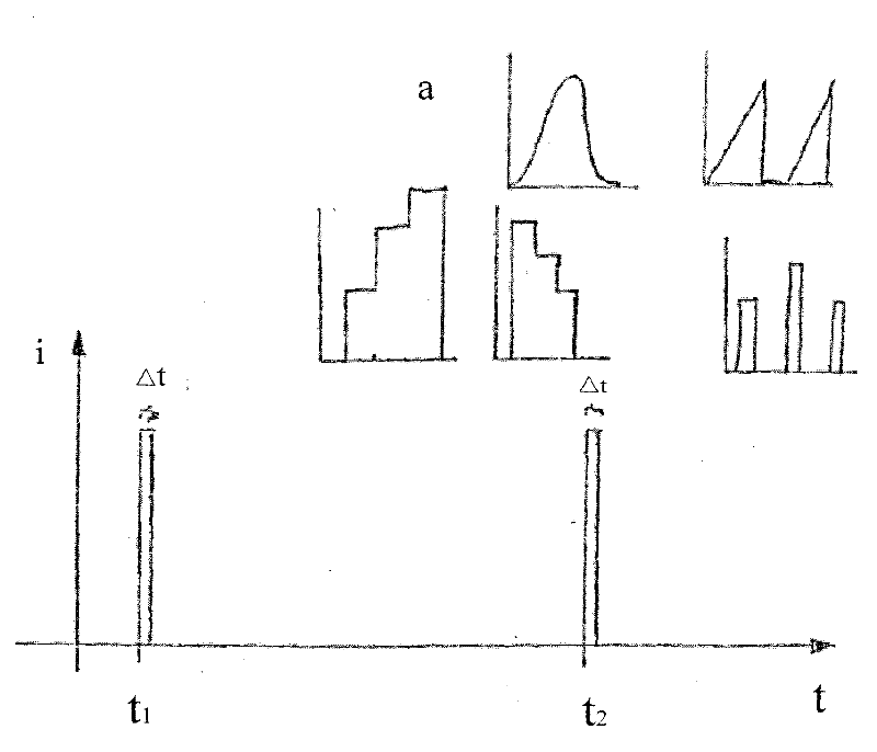
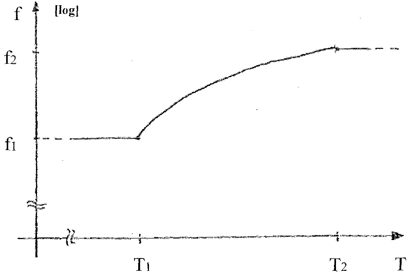
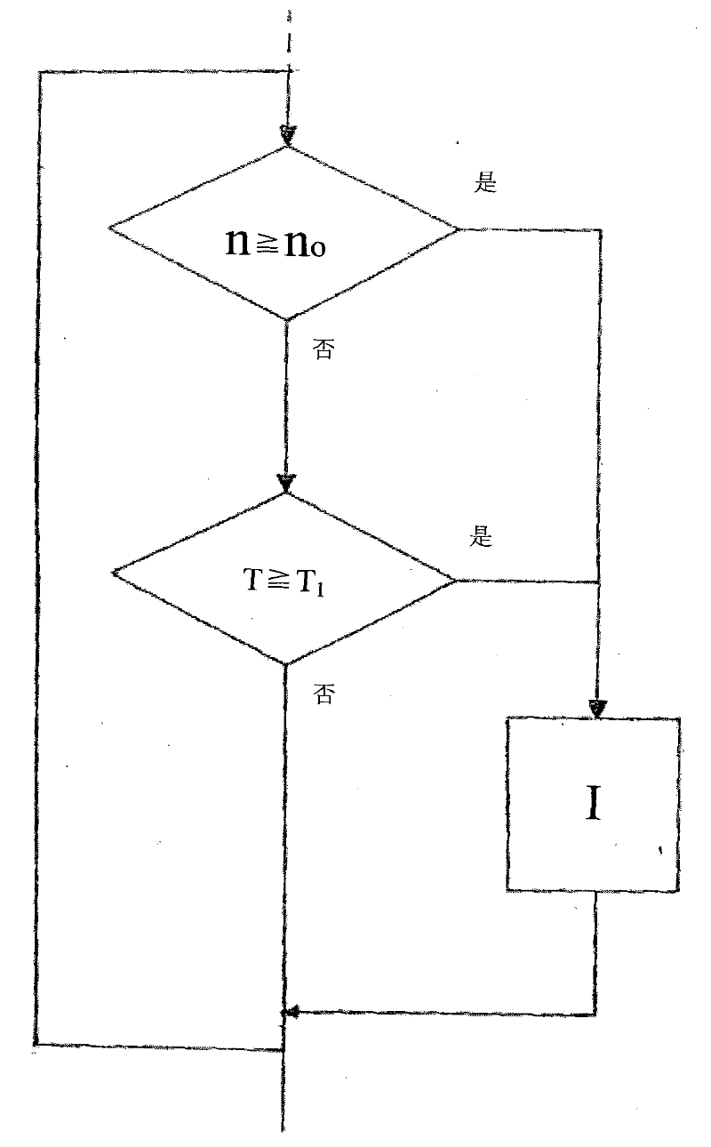

Image

  • Method for operating a retarder
  • Method for operating a retarder
  • Method for operating a retarder

Examples


Embodiment Construction

[0026] The speed reducer installed in the vehicle power transmission system is common and typical for professionals in the field of speed reducer technology as a wear-free braking device, so the specific content of the operating method designed by the present invention will not be discussed. describe. Fundamentally, the various structures of hydrodynamic reducers are applicable to the use of the reducer operation method, regardless of whether they use oil, water and / or water mixture as the working medium.

[0027] The manner in which the retarder is filled with working medium for the braking operation is not or only a secondary effect of the invention. Fundamentally, it is conceivable and common to fill the working chamber of the reducer with suitable arrangements, such as solenoid valves, working medium in the corresponding reservoir, which has a higher pressure than the working chamber. As long as the valve is opened, the working medium will flow into the working chamber of...


PUM


Abstract

The invention relates to a method for operating a hydrodynamic retarder having at least one working chamber that is filled with a working medium in braking mode, and substantially emptied in non-braking mode. According to the invention, a prescribed amount of working medium is pulsingly brought into the working chamber of the retarder in non-braking mode. This can occur either constantly, or as a function of suitable measurement variables.

Description

technical field [0001] The invention relates to an operation method of a hydrodynamic reducer containing at least one working chamber. Background technique [0002] The use of retarders as wear-free brakes is a common state-of-the-art technology, especially in public transport. The speed reducer is usually directly connected to the secondary output section of an internal combustion engine or transmission or cardan shaft of these vehicles. The reducer in operation is filled with working medium, usually oil or water, or a water mixture. During the braking operation, the working medium in the working chamber of the hydrodynamic reducer is driven to circulate by the bladed rotor of the reducer, so that the rotation of the rotor of the hydrodynamic reducer is transmitted to the bladed stator or the bladed counter of the rotor The rotor, which in turn leads to hydrodynamic braking of the rotor, thereby producing the braking effect of the reducer. In non-braking operation, the w...

Claims


Application Information

Patent Timeline
Patent Type & Authority Applications(China)
IPC IPC(8): B60T10/02
CPCB60T10/02B60T1/08
Inventor 蒂尔曼·胡特于尔根·贝茨罗兰·舍雷尔
Owner VOITH PATENT GMBH
Learn More