Multi-beam exposure scanning method and apparatus, and method for manufacturing printing plate

An exposure scanning, multi-beam technology, used in multi-beam exposure scanning and equipment, as well as in the field of manufacturing printing plates, can solve problems such as difficult to stabilize small dots and fine lines of fine shapes, and achieve the effect of optimizing the amount of light

Inactive Publication Date: 2011-11-09
FUJIFILM CORP
View PDF1 Cites 2 Cited by
  • Summary
  • Abstract
  • Description
  • Claims
  • Application Information

AI Technical Summary

Problems solved by technology

When engraving a plate using this multi-beam exposure technique, it is very difficult to stably form fine shapes such as small dots and thin lines due to the influence of heat caused by adjacent beams

Method used


Image

  • Multi-beam exposure scanning method and apparatus, and method for manufacturing printing plate
  • Multi-beam exposure scanning method and apparatus, and method for manufacturing printing plate
  • Multi-beam exposure scanning method and apparatus, and method for manufacturing printing plate

Examples


no. 2 example

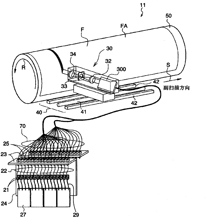
[0076] The above-mentioned first embodiment exemplifies where by using as reference image 3 An exposure head 30 is described with an array arrangement of optical fibers in a column, whereas a beam arrangement of beams of 32 lines (one trace) is arranged obliquely in a column. However, when carrying out the present invention, the beam arrangement is not limited to this one-column arrangement.

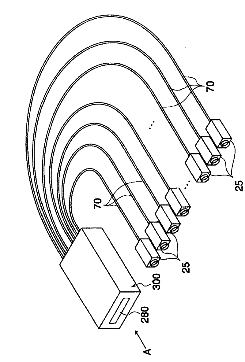
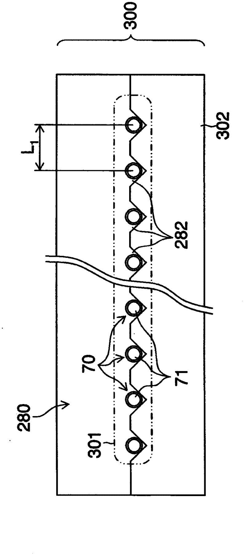
[0077] Figure 13 An example of another optical fiber array unit light source is shown. Figure 13 The illustrated fiber array unit light source 500 includes fiber array units 501, 502, 503, and 504 combined in four stages. In each array of stages of the fiber array unit light source 500 , 16 optical fibers 70 having a core diameter of 105 μm are linearly arranged in one column, and a total of 64 optical fibers 70 of four stages are arranged in the shape of an oblique matrix.

[0078] as in Figure 13 As shown in , in the case where, from the right end Set the channel label for the...


PUM

PropertyMeasurementUnit
diameteraaaaaaaaaa

Abstract

In a multi-beam exposure scanning method, when an irradiation region, which is a region on an object to be irradiated with a single beam, is exposed, the light quantity of the beam is controlled based on an exposed state of another irradiation region around the irradiation region to be exposed. When the other irradiation region near a periphery of the irradiation region to be exposed has not been exposed, the irradiation region is irradiated with a beam having a first light quantity. When the other irradiation region has been exposed, the irradiation region is irradiated with a beam having a second light quantity smaller than the first light quantity. Accordingly, influence of heat due to an adjacent beam can be effectively reduced.

Description

technical field [0001] The invention relates to a multi-beam exposure scanning method and equipment. More particularly, the present invention relates to a multi-beam exposure scanning technique suitable for manufacturing a printing plate such as a flexographic plate, and to a manufacturing technique of a printing plate to which the multi-beam exposure scanning technique is applied. Background technique [0002] Conventionally, there has been disclosed a technique of engraving a concave shape on the surface of a plate by using a multi-beam head capable of simultaneously emitting a plurality of laser beams (Japanese Patent Application Laid-Open No. 09-85927). When engraving a plate using such a multi-beam exposure technique, it is very difficult to stably form fine shapes such as small dots and thin lines due to the influence of heat caused by adjacent beams. [0003] In order to solve such a problem, Japanese Patent Application Laid-Open No. 09-85927 proposes a configuration...

Claims


Application Information

Patent Timeline
Patent Type & Authority Applications(China)
IPC IPC(8): G03F7/20B41C1/05G03F7/24
CPCG03F7/24B41C1/05G03F7/2055
Inventor 宫川一郎
Owner FUJIFILM CORP
Why Eureka
Try Eureka