
hammer mill

A hammer mill and hammer technology, applied in grain processing and other directions, can solve the problems of low output of the mill, troubled by the improvement of mill technology, poor uniformity, etc. degree of effect

Active Publication Date: 2015-08-19
上海春谷机械制造有限公司
View PDF8 Cites 0 Cited by
  • Summary
  • Abstract
  • Description
  • Claims
  • Application Information

AI Technical Summary

Problems solved by technology

[0006] Due to the above two points, the output of the pulverizer is low and the uniformity is poor. For a long time, this is one of the key problems that plague the improvement of pulverizer technology.

Method used


Image

  • hammer mill
  • hammer mill
  • hammer mill

Examples


Embodiment 1

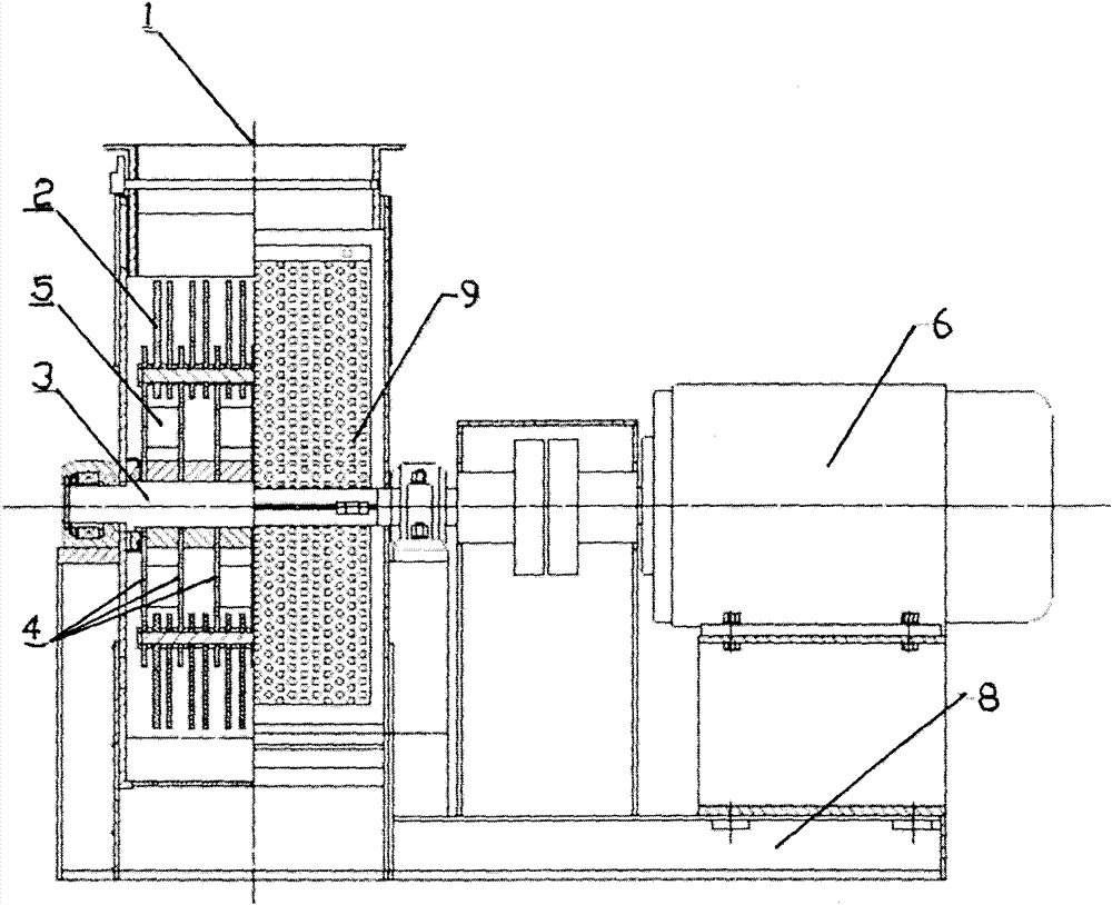
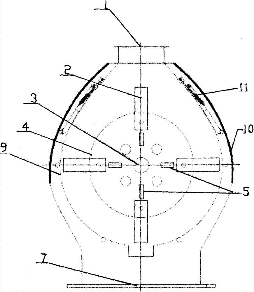
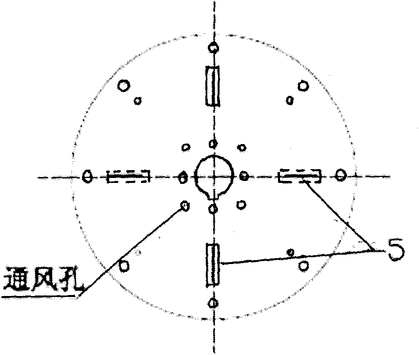
[0016] Example 1: figure 1 , figure 2 , a horizontal pulverizer, pulverizer inlet (1), hammer (2), rotor (3), turntable (4) mounted on the rotor, wind blades (5), motor (6), pulverizer Machine discharge port (7), machine body (8), sieve sheet (9), door (10), press screen frame (11) etc. are composed. its rotor image 3 , the fan blades are installed between the turntables, and 2 fan blades are installed between each 2 turntables. The direction of the two fan blades is 180 degrees, on the same line passing through the center of the circle, and the distance from the center of the circle is equal. The distance between adjacent turntables The fan blades are staggered at 90 degrees, so that not only vertical wind pulsation but also horizontal wind movement can be formed on the inner surface of the screen, which destroys the uniform centrifugal force inside the screen and the negative pressure outside the screen, and makes the qualified materials more efficient. It is easy to si...


PUM


Abstract

The invention relates to a hammer pulverizer, which comprises a feed inlet (1), hammers (2), a rotor (3), rotary plates on the rotor (4), blades (5), a motor (6), a discharge hole of the pulverizer (7), a body of the pulverizer (8), sieve sheets (9), a door (10) and pressurized screen frames (11), wherein, the blades (5) are added between the rotary plates, two sheets of the blades formed with 180 DEG in each shift are arranged in line shape, blades in adjacent two shifts are taken as a right angle with each other, the rotary plates (4) opens a plurality of vent holes at the place close to a rotating shaft. Therefore, wind can be inlet from the gap of the shaft holes at two sides of the pulverizer when the rotor rotates, and then wind is passed through the vent holes of the rotary plates, partial material of ineffective motion stored in the central rotor can be pushed to hammers terminus and crushed by the hammers under the fanning of the blades, simultaneously, wind pressure with changing pulse is provided by the blades which destroys the uniformly centrifugal force of a material ring in the sieve and the negative pressure outside the sieve, thereby the output and the uniformity of the material can be raised, the screen blinding phenomenon can be improved.

Description

technical field [0001] The invention relates to a hammer mill, which is usually used in feed, grain, food, chemical, medical and other industries. Background technique [0002] This type of pulverizer usually consists of a pulverizer inlet (1), a hammer (2), a rotor (3), a turntable mounted on the rotor (4), a motor (6), a pulverizer outlet (7), Body (8), sieve sheet (9), door (10), press screen frame (11) etc. are formed. When working, the rotor (3) is driven by the motor (6) to rotate the hammer (2) on the rotor (3), and the material is continuously pulverized by the hammer (2) after entering from the feed port (1). Qualified powder passes through the sieve hole of the sieve (9) and is discharged from the discharge port (7) of the pulverizer. [0003] This type of shredder has the following problems: [0004] 1. After the material enters the pulverizer, the material moves in the same direction as the hammer. Under the action of centrifugal force, the surface of the scre...

Claims


Application Information

Patent Timeline
Patent Type & Authority Patents(China)
IPC IPC(8): B02C13/04B02C13/288
Inventor 俞信国乐其呈俞正
Owner 上海春谷机械制造有限公司
Learn More