High-rigidity rolling mill

A high-rigidity, rolling mill technology, applied in the direction of metal rolling stand, metal rolling mill stand, metal rolling, etc., can solve the problem of increasing the oil pressure of the hydraulic pressing system, increasing the cross-sectional size of the stand, and increasing the diameter of the pressing screw and other problems, to achieve the effect of improving longitudinal stiffness, realizing constant roll gap control, and reducing vertical deformation

Active Publication Date: 2011-11-16
UNIV OF SCI & TECH BEIJING
View PDF4 Cites 0 Cited by
  • Summary
  • Abstract
  • Description
  • Claims
  • Application Information

AI Technical Summary

Problems solved by technology

[0004] As far as internal factors are concerned, the commonly used method is to increase the section size of the frame, increase the diameter of the support roller, increase the diameter of the pressing screw or increase the oil pressure of the hydraulic pressing system, but this approach often makes the machine base extremely large

Method used


Image

  • High-rigidity rolling mill
  • High-rigidity rolling mill
  • High-rigidity rolling mill

Examples


Embodiment Construction

[0020] The technical solutions of the present invention will be clearly and completely described below in conjunction with the accompanying drawings of the present invention. Apparently, the described embodiments are only some of the embodiments of the present invention, not all of them. Based on the embodiments of the present invention, all other embodiments obtained by persons of ordinary skill in the art without creative efforts fall within the protection scope of the present invention.

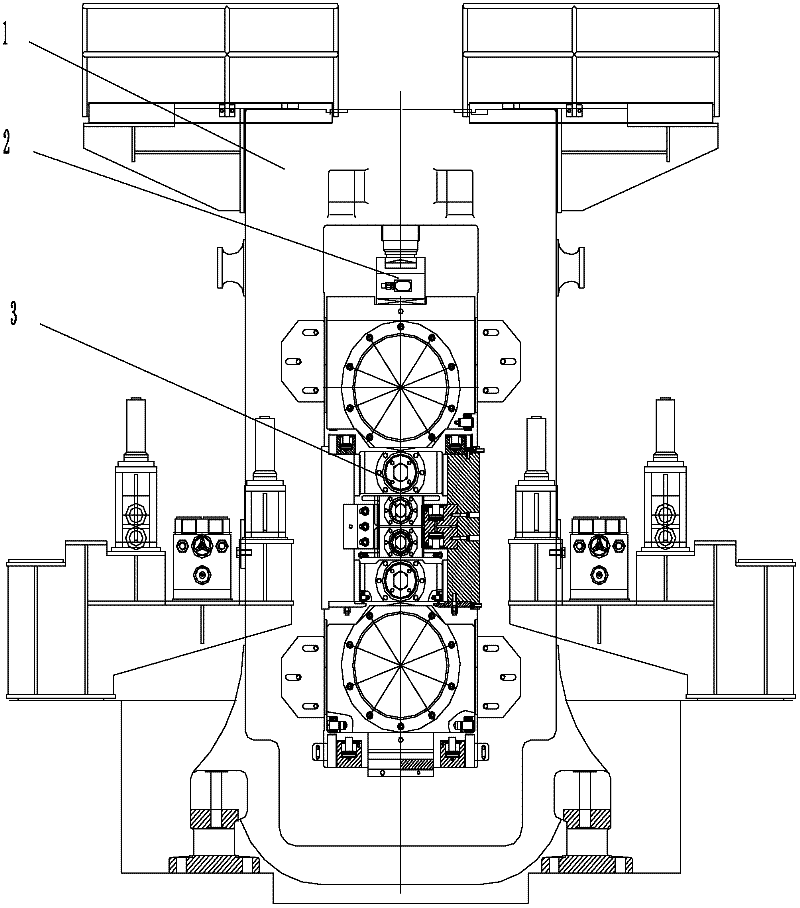
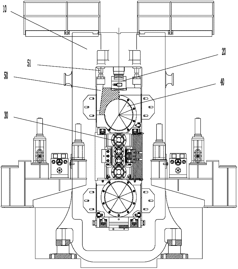
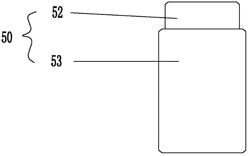
[0021] Such as figure 2 As shown, the embodiment of the high-rigidity rolling mill provided by the present invention includes a stand 10, a reduction system 20 and a roll system 30, and an upper support roll bearing housing 40 is arranged between the reduction system 20 and the roll system 30, A compression wedge block 50 is also provided between the frame 10 and the upper support bearing seat 40, and the compression wedge block 50 is upwardly connected with a compression hydraulic cylind...


PUM


Abstract

The invention discloses a high-rigidity rolling mill and belongs to the technical field of metal pressure processing. The high-rigidity rolling mill comprises a stander, a press-down system and a roller system, wherein an upper backup roller bearing pedestal is arranged between the press-down system and the roller system; a compaction inclined wedge block is arranged between the stander and the upper backup roller bearing pedestal; the compaction inclined wedge block is upward connected with a compaction hydraulic cylinder; the compaction hydraulic cylinder is fixedly connected with the stander; and the compaction inclined wedge block is downward spliced with the upper backup roller bearing pedestal to form a self-locking state. The high-rigidity rolling mill has the characteristics of high rigidity and high milling precision.

Description

technical field [0001] The invention relates to a high-rigidity rolling mill, in particular to a high-rigidity rolling mill suitable for high-precision plate and strip processing, and belongs to the technical field of metal pressure processing. Background technique [0002] With the continuous development of steel rolling technology, rolling mills of various roll systems and roll types have appeared one after another, and the reduction system, hydraulic servo system and computer control system have made great progress, which has greatly improved the manufacturing precision and control precision of rolled pieces. Big improvement. However, for the rolling mill itself, the stress deformation and vibration of its parts still have a great impact on improving the stiffness and rolling precision of the rolling mill, such as figure 1 As shown, the deformation of the three main components of the frame system 1, the pressing system 2 and the roll system 3 is the main reason for affec...

Claims


Application Information

Patent Timeline
Patent Type & Authority Applications(China)
IPC IPC(8): B21B1/22B21B31/02
Inventor 康永林张凤泉
Owner UNIV OF SCI & TECH BEIJING
Why Eureka
Try Eureka