Fixing frame of electronic device

An electronic device and a fixing frame technology, applied in the fixing frame field, can solve the problems of general products having no suitable structure and inconvenience, etc.

Inactive Publication Date: 2011-11-16
TAIDING TECH
View PDF8 Cites 3 Cited by
  • Summary
  • Abstract
  • Description
  • Claims
  • Application Information

AI Technical Summary

Problems solved by technology

[0006] It can be seen that the above-mentioned existing electronic device fixing frame obviously still has inconvenience and defects in structure and use, and needs to be further improved urgently.
In order to solve the above-mentioned problems, the relevant m

Method used


Image

  • Fixing frame of electronic device
  • Fixing frame of electronic device
  • Fixing frame of electronic device

Examples


Embodiment Construction

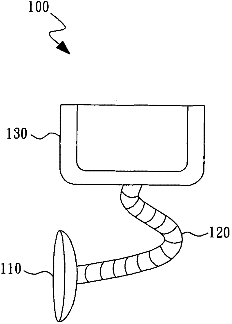
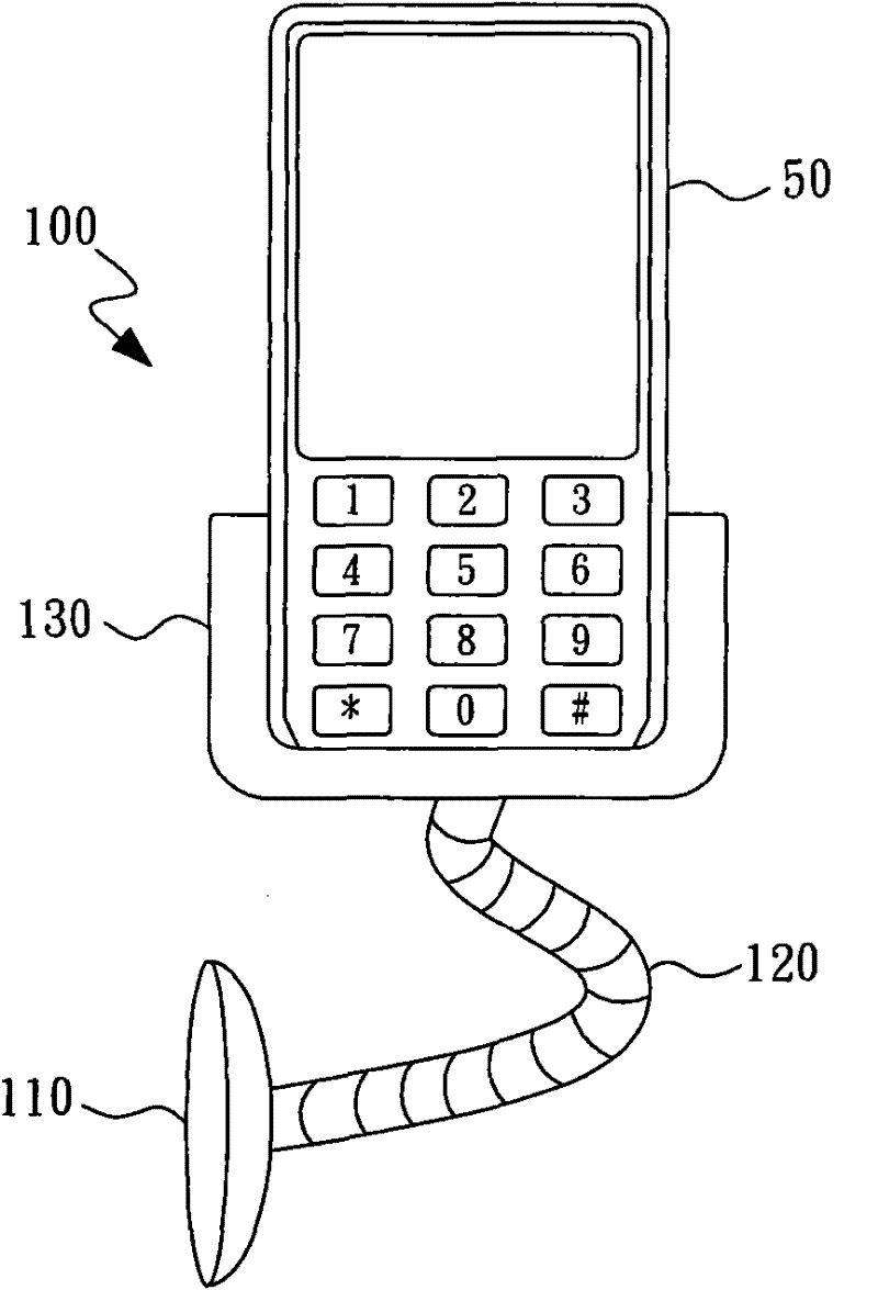
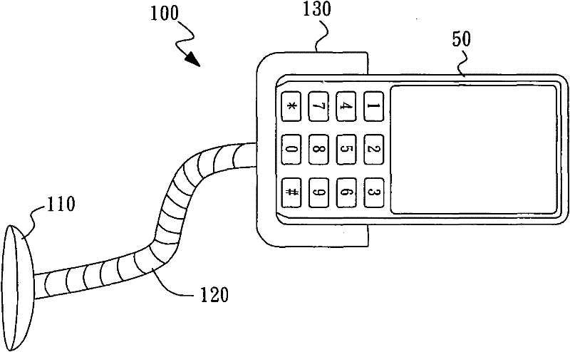
[0040] In order to further explain the technical means and effects of the present invention to achieve the intended purpose of the invention, the specific implementation, structure, characteristics and effects of the electronic device fixing frame proposed according to the present invention will be described below in conjunction with the accompanying drawings and preferred embodiments. , as detailed below.

[0041] Some embodiments of the present invention will be described in detail as follows. However, in addition to the following descriptions, the present invention can also be widely implemented in other embodiments, and the protection scope of the present invention is not limited by the embodiments, which shall prevail by the protection scope of the claims. Furthermore, in order to provide a clearer description and an easier understanding of the present invention, the various parts in the drawings have not been drawn according to their relative sizes, and some dimensions h...


PUM


Abstract

The invention relates to a fixing frame of an electronic device. The fixing frame comprises a fixing seat, a sucker device and a supporting frame, wherein the sucker device is arranged on the fixing seat and comprises at least one sucker used for fixing the electronic device; and the fixing seat can rotate relative to the supporting frame by a proper angle, wherein the rotation movement of the fixing seat can provide required power for absorbing the electronic device.

Description

technical field [0001] The invention relates to a fixing frame, in particular to an electronic device fixing frame. Background technique [0002] With the advancement of technology, hand-held electronic devices have become popular among ordinary consumers. Hand-held electronic devices include mobile phones, personal digital assistants (personal digital assistant, PDA), global positioning system (global positioning system, GPS), etc., which can be accessed at any time Provide various information. For example, the above-mentioned hand-held electronic device can be fixed in an appropriate position, so as to grasp various information when driving a vehicle. [0003] Figure 1A It is a schematic diagram showing a conventional electronic device fixing bracket. The electronic device fixing frame 100 includes a suction cup 110 , a flexible supporting frame 120 and a fixing base 130 . The suction cup 110 can be adsorbed on the windshield of the car to fix the electronic device fix...

Claims


Application Information

Patent Timeline
IPC IPC(8): F16M11/04F16M11/18F16B47/00B60R11/02
Inventor 罗南平
Owner TAIDING TECH
Why Eureka
Try Eureka