
Bulk feeder

A feeder and bulk material technology, applied in the direction of conveyor objects, electrical components, transportation and packaging, etc., can solve problems such as low efficiency and difficulty in utilizing the capacity of the loader

Active Publication Date: 2013-12-04
TAIYO YUDEN KK
View PDF6 Cites 0 Cited by
  • Summary
  • Abstract
  • Description
  • Claims
  • Application Information

AI Technical Summary

Problems solved by technology

However, in the above-mentioned bulk feeder, since the efficiency of supplying parts to the take-out port is low as described above, it is difficult to exhibit the ability to adapt to a high-speed loader, that is, the ability to supply parts to the take-out port at short time intervals.

Method used


Image

  • Bulk feeder
  • Bulk feeder
  • Bulk feeder

Examples


Embodiment Construction

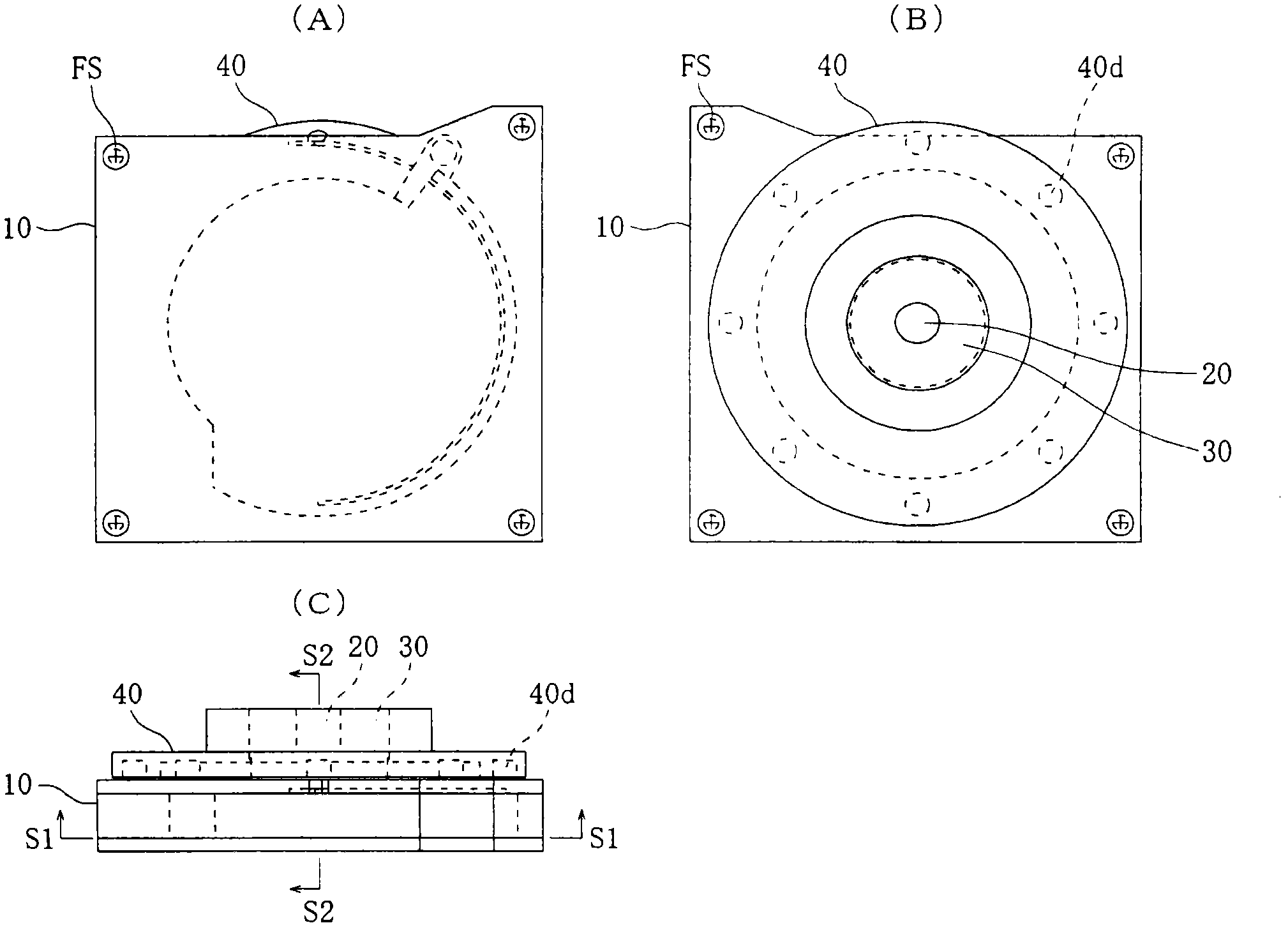
[0051] Embodiments of the present invention will be described below, and the terms "identical" and "identical" used in the description include tolerances in dimensions, and do not mean complete coincidence or complete identity. Also, in the following description, the figure 2 The left, right, front and depth of (A) and other pictures (except figure 1 (A)~ figure 1 The corresponding directions of (C)) are called front, back, left and right, respectively.

[0052] Parts to be supplied by bulk material feeders

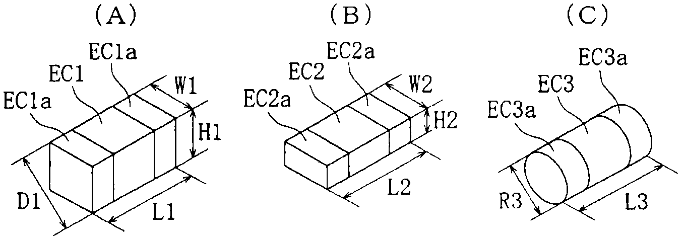
[0053] First, quote figure 1 (A), explain figure 2 (A)~ figure 2 Parts shown in (C) that are to be supplied by the bulk material feeder.

[0054] like figure 1 As shown in (A), the component EC1 is formed in a cuboid shape having a dimensional relationship of length L1>width W1=height H1. Specific examples of this component EC1 are electronic components such as small chip capacitors and chip registers whose length L1 is 1.6 mm, 1.0 mm, 0.6 mm, or 0.4 mm. Any e...


PUM


Abstract

The present invention provides a bulk feeder capable of supplying components to a take-out port at short time intervals. The bulk material feeder includes: a box (10) with a storage chamber (14), a guide groove (13b), an inlet (15a), a supply passage (15), a stop bar (13e) and an outlet (16). ); and a rotating part (40) with a plurality of permanent magnets (40d). This bulk material feeder is constituted, uses the stop bar (13e) that can be magnetized by the magnetic force of permanent magnet (40d), and in addition, the magnetic pole of one side of permanent magnet (40d) crosses over take-off port (16) ) as a standby position for parts removal, in which the stop bar (13e) is magnetized by the magnetic force of the stopped permanent magnet (40d), and the magnetized stop bar (13e) The magnetic force attracts the component (EC1) that is in contact with the stopper bar (13e).

Description

technical field [0001] The present invention relates to a bulk feeder that supplies components stored in a scattered state (a state in which orientations do not match) in a storage chamber to a take-out port in a predetermined orientation. Background technique [0002] In Patent Documents 1 and 2, a bulk material feeder is disclosed, which includes: a storage chamber having a rear wall surface and an arc-shaped guide surface on the outer periphery; inlet); a passage provided downstream from the inlet; a component separation part provided at the front end of the passage; a rotating plate arranged behind the wall surface of the storage chamber; and a plurality of magnets arranged on the rotating plate. [0003] In addition, Patent Documents 1 and 2 disclose the function of rotating the rotating plate in a predetermined direction with the components stored in the storage chamber in a scattered state (in a state where the directions are not aligned), and the storage is moved by ...

Claims


Application Information

Patent Timeline
Patent Type & Authority Patents(China)
IPC IPC(8): B65G47/14H05K13/02
CPCB65G47/1485B65G47/14H05K13/02
Inventor 齐藤浩二
Owner TAIYO YUDEN KK
Learn More