
Electric power inspection robot system based on three-dimensional laser radar and mapping method

A robot system and inspection robot technology, applied in radio wave measurement system, control/adjustment system, two-dimensional position/channel control, etc. Inaccurate data and other problems, to achieve clear structural features, high real-time performance, and improve control accuracy

Pending Publication Date: 2022-03-04
HANGZHOU DIANZI UNIV +2
View PDF0 Cites 0 Cited by
  • Summary
  • Abstract
  • Description
  • Claims
  • Application Information

AI Technical Summary

Problems solved by technology

[0005] The purpose of the present invention is to overcome the deficiencies of the prior art, provide a three-dimensional laser radar-based power inspection robot system architecture design and mapping method, adopt a layered control method to improve control efficiency and control accuracy, and a professional control framework It can improve the system logic, solve the problem of large amount of 3D laser radar data, complex processing algorithm, and long time to build a map, and solve the problem of building a map based on laser SLAM. In a strong light environment, the obtained positioning data of the robot is inaccurate. When there are many dynamic obstacles, the problem of unstable positioning and mapping

Method used


Image

  • Electric power inspection robot system based on three-dimensional laser radar and mapping method
  • Electric power inspection robot system based on three-dimensional laser radar and mapping method
  • Electric power inspection robot system based on three-dimensional laser radar and mapping method

Examples


Embodiment 1

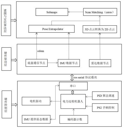
[0038]A kind of power inspection robot system based on three-dimensional laser radar of the present invention, see figure 1 As shown, the system architecture described in the present invention includes a hardware control layer, a hardware driver layer, and a mapping and positioning algorithm layer.

[0039] The hardware control layer has a PS2 handle that sends control signals to the power inspection robot, and uses the PID algorithm to adjust the speed through the working state of the motor driven by the motor, and then controls the motion of the power inspection robot. At the same time, the encoder and IMU are used to obtain the speed and attitude of the power inspection robot, and the speed and attitude data are sent to the hardware driver layer through the ros serial protocol. The hardware driver layer obtains the wheel odometer (odom) through the chassis communication node Information, IMU data information, 3D point cloud data is obtained through the radar data node, and ...


PUM


Abstract

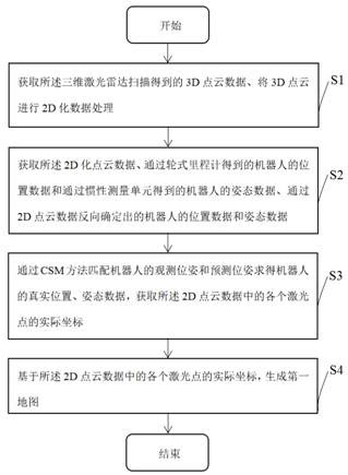
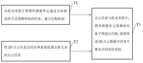
The invention discloses an electric power inspection robot system based on a three-dimensional laser radar and a mapping method, the system architecture comprises a hardware control layer, a hardware driving layer and a mapping and positioning algorithm layer, the method comprises the following steps: obtaining 3D point cloud data obtained by scanning of the three-dimensional laser radar, and carrying out 2D data processing on the 3D point cloud; obtaining the 2D point cloud data, the position data of the robot obtained through a wheel type odometer and the posture data of the robot obtained through an inertial measurement unit, namely, the predicted posture of the robot, and the position data and the posture data of the robot reversely determined through the 2D point cloud, namely, the observation posture of the robot; matching the observation pose and the prediction pose of the robot through a CSM method to obtain the real position and pose data of the robot, and obtaining the actual coordinates of each laser point in the 2D point cloud data; and generating a first map based on the actual coordinate of each laser point in the 2D point cloud data.

Description

technical field [0001] The invention relates to the technical field of inspection robot equipment, in particular to a three-dimensional laser radar-based power inspection robot system and a mapping method. Background technique [0002] With the development of the economy and the improvement of people's living standards, social power consumption continues to increase, posing higher challenges to the stability of power grid operation, and the demand for inspections in various links of power systems such as power transformation, power transmission, and power distribution has further increased. Power substations are faced with the demands of high reliability, high load density and high power quality. The requirements for power outages are becoming more and more stringent, and there are fewer and fewer opportunities for offline operation and maintenance of key substation equipment. Therefore, the power substation urgently needs advanced on-site maintenance operation technology. ...

Claims


Application Information

Patent Timeline
Patent Type & Authority Applications(China)
IPC IPC(8): G05D1/02G01S17/89
CPCG05D1/024G05D1/0221G01S17/89
Inventor 吴秋轩周忠容曾平良田杨阳毛万登孟秦源张波涛袁少光耿俊成赵健
Owner HANGZHOU DIANZI UNIV
Learn More