Damping device having centrifugal force pendulum

A vibration damping device and centrifugal pendulum technology, applied in the direction of rotation vibration suppression, spring/shock absorber, vibration suppression adjustment, etc., can solve the problems of limited mass inertia and reduced efficiency of centrifugal pendulum

Active Publication Date: 2011-11-16
SCHAEFFLER TECH AG & CO KG
View PDF4 Cites 43 Cited by
  • Summary
  • Abstract
  • Description
  • Claims
  • Application Information

AI Technical Summary

Problems solved by technology

Here, the mass of the pendulum flange does not contribute to damping, but requires radial and axial installation space
The freely oscillating pendulum mass must therefore be reduced by the material width of the pendulum flange, so that the achievable mass inertia of the pendulum mass is strongly limited due to structural space reasons and thus the efficiency of the centrifugal pendulum is reduced

Method used


Image

  • Damping device having centrifugal force pendulum
  • Damping device having centrifugal force pendulum
  • Damping device having centrifugal force pendulum

Examples


Embodiment Construction

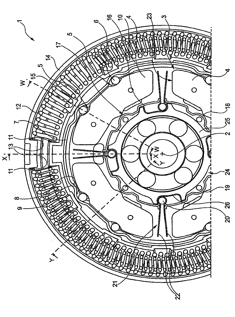
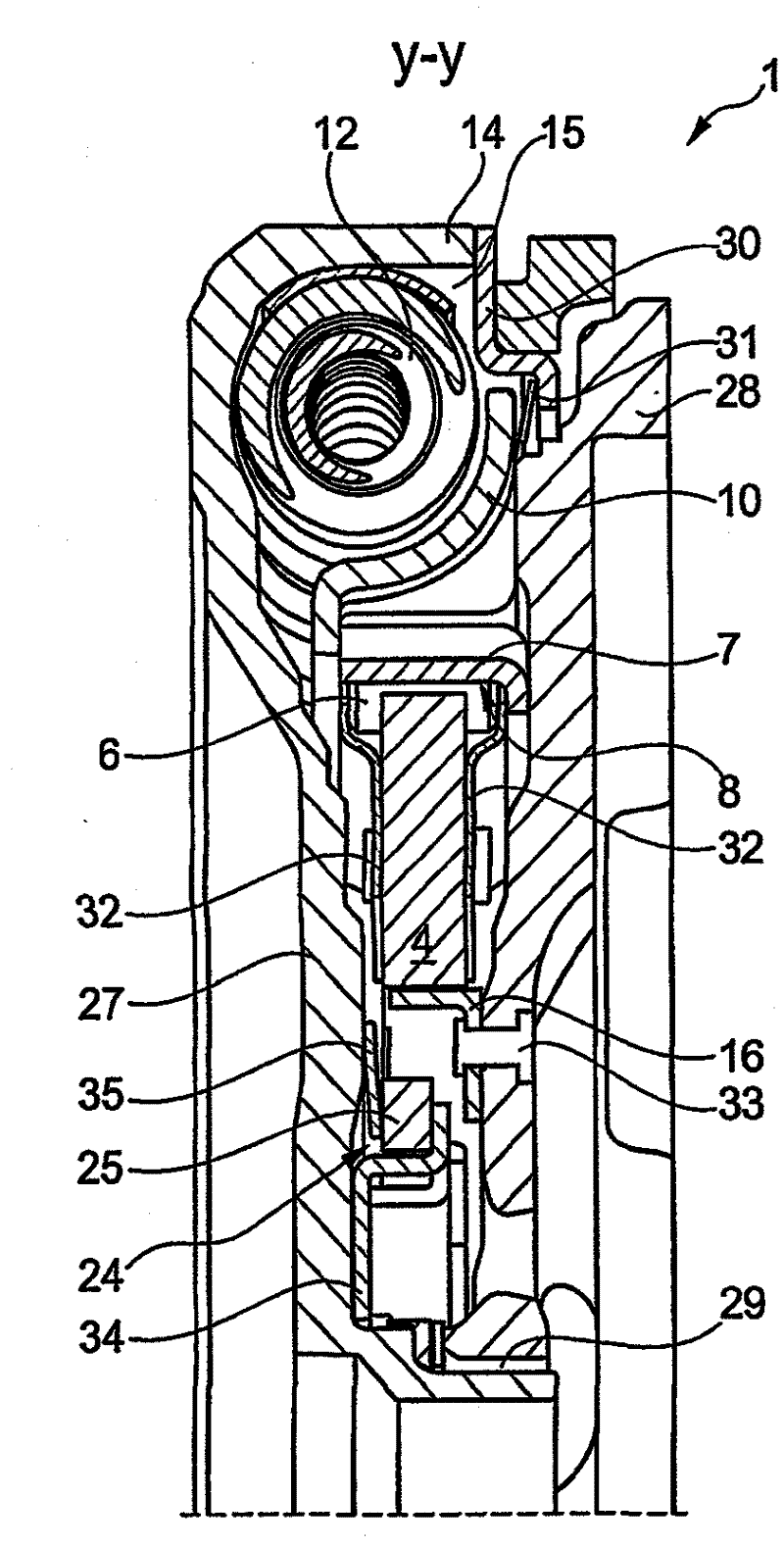
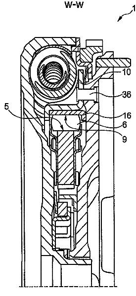
[0013] figure 1 The damping device 1 is shown in a partial view, wherein a section perpendicular to the axis of rotation 2 is drawn and the inner parts of the damping device 1 are thus seen. The damping device 1 comprises a centrifugal pendulum 3 comprising four pendulum masses 4 distributed over the circumference, each of which has two paths of motion 5 radially on the outside, formed in the exemplary embodiment shown by rollers The rolling body 6 rolls on the moving track 5. On the diametrically opposite side, a ring element 7 is provided, which has a receiving profile 8 with a movement path 9 complementary to the movement path 5, on which the rolling bodies 6 also roll, This allows the pendulum mass 4 to pivot relative to the ring 7 up to a maximum pivot angle.

[0014] The ring part 7 is fixedly connected to a radially inner molded part 10 which is assigned to the secondary flywheel mass of the damper device 1 and which has a loading area 11 for an energy store 12 desig...


PUM


Abstract

The invention relates to a damping device comprising two centrifugal masses, which are supported on each other and can be rotated to a limited extent with respect to each other against the action of at least one energy accumulator accommodated in a radially outwardly disposed annular chamber, and comprising a centrifugal force pendulum which comprises several pendulum masses distributed over the circumference and is effectively associated with a centrifugal mass. According to the invention, the pendulum masses are pivotably supported to a limited extent radially inside, and within the axial installation space of the annual chamber radially outside, on a receiving profile, which is effectively connected to the centrifugal mass, by way of rolling bodies.

Description

technical field [0001] The invention relates to a vibration damping device with two flywheel masses which are mutually supported in a limited torsion against the action of at least one energy store, said flywheel masses having a centrifugal force arranged effectively on one of the flywheel masses put. Background technique [0002] The preferred fields of application of the invention are split flywheels such as dual mass flywheels and similar damping devices, such as with hydraulic torque converters, dual clutch damping devices and vibration damping devices in conical-disc winding belt transmissions Such a vibration damping device used in combination. Such a damping device has two mutually supported, twistable disks around a common axis of rotation, such as flywheel masses, which can act against at least one energy accumulator (for example, helical coils such as bow springs distributed on the circumference). Spring) acts to twist relative to each other. One of these discs,...

Claims


Application Information

Patent Timeline
Patent Type & Authority Applications(China)
IPC IPC(8): F16F15/134F16F15/14
CPCF16F15/145
Inventor W·赖克H·蒙德J·克罗尔A·库伊
Owner SCHAEFFLER TECH AG & CO KG
Why Eureka
Try Eureka